Quick answer: what does MPO endface inspection prove?

MPO endface inspection documents visible contamination, scratches and defects within an approved inspection scope. It does not prove ferrule geometry, insertion loss, return loss or polarity. A complete acceptance plan links the inspection result to separate geometry, optical and fiber-map records for the same identified assembly or controlled sample.
An MPO end-face report marked “PASS” is useful only if it identifies the test or inspection, requirement, assembly and result. A microscope image cannot establish insertion loss. An interferometer report does not show whether the shipped ferrule remained clean. A low-loss result does not confirm the fiber map.
For a purchase specification or first-article plan, keep four evidence records separate and link them to the same part, revision, unit or lot.
| Acceptance question | Primary evidence | What it can establish | What it does not establish by itself |
|---|---|---|---|
| Is the rectangular ferrule geometry within the approved requirement? | 3D interferometry record using the approved rectangular-ferrule method and interface limits | Measured geometry fields for the identified end face | Cleanliness at shipment, IL/RL or polarity |
| Is the ferrule surface fit for the defined inspection state? | Visual-inspection images and analysis under the approved IEC 61300-3-35:2022 plan | Debris, scratches and visible defects within the stated inspection scope | Geometry, attenuation, return loss or fiber mapping |
| Does the assembly meet its optical requirement? | IL/RL records under the approved method, wavelength, reference setup and limits | Measured optical performance of the stated path | End-to-end polarity or a complete geometry assessment |
| Does the fiber map match the channel design? | Polarity/continuity record against the controlled map | Position-to-position mapping for the identified assembly | Cleanliness, geometry or optical margin |
Procurement summary
Before approving an MPO assembly, freeze the drawing revision, fiber arrangement, mode, interface, polish, pin state, mating reference and project requirements. Then request only the geometry, visual, IL/RL and polarity records required by the buyer-approved quality plan. Every record should identify the same unit, lot or controlled sample and disclose its method, limits, exceptions and disposition. Compare supplier price and lead time only after report granularity, retained data, sample or first-article work and document handling are normalized. An unexplained “PASS” remains an evidence gap, not a release decision.
Five conclusions to carry into the RFQ
- Visual inspection, interferometry, IL/RL testing and polarity verification answer different questions.
- A method or standard citation is useful only when its edition and configuration scope match the ordered assembly.
- Unit-, lot- and sample-level reports are different deliverables and may change document effort and quotation scope.
- Cleaning may resolve removable contamination; it cannot correct geometry, polarity or an optical-path failure.
- Release requires traceability, exception history and an authorized disposition—not merely a supplier PASS label.
BWNFiber review principle: one MPO “PASS” is not a release packet. The useful question is whether every required record applies to the same identified configuration and supports the decision being made.
Choose the right guide: Continue here if you are writing an RFQ, reviewing first-article evidence or deciding whether an MPO evidence packet is complete. Use the fiber cleaning guide for clean-and-reinspect technique, the fiber testing guide for installed-link test methods, or the MPO trunk installation guide for routing, mating and commissioning.
Already reviewing a supplier packet? Send BWNFiber the configuration and list of available reports for a document-gap review. Do not include proprietary drawings or controlled data unless the approved inquiry channel allows it.
On this page
- Freeze the MPO configuration
- Read the geometry record and select the correct instrument
- Review visual-inspection evidence
- Connect geometry, visual, optical and polarity records
- Define auditable supplier-report fields
- Compare supplier evidence, price and lead time
- Resolve buyer objections before release
- Localize international evidence requirements
- Copy the RFQ/first-article evidence clause
Freeze the MPO configuration before selecting limits

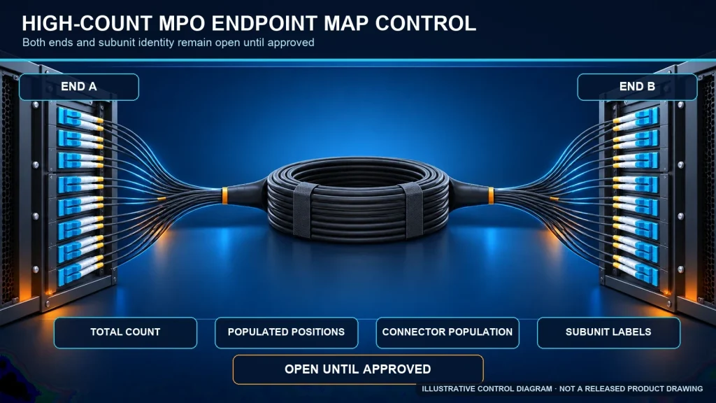
Do not begin with a generic line such as “MPO, IEC compliant.” Begin with the interface being approved. Record at least:
- product or drawing number and revision;
- fiber count and row arrangement;
- the single-mode or multimode category declared on the drawing, such as OS2 or OM3/OM4/OM5 where applicable;
- flat or angled physical-contact interface, including the supplier’s UPC/APC designation where used;
- mating interface and key orientation;
- pinned or unpinned state where it affects the inspection fixture or mating plan;
- ferrule/interface family and material where the requirement depends on it;
- intended evidence: geometry, visual condition, IL/RL, polarity, or all four;
- applicable document number, edition, project limit and report format.
IEC 61755-3-31:2015 addresses an angled PPS rectangular ferrule optical interface for non-dispersion-shifted single-mode physically contacting fibers. It is not a universal limit table for every MPO mode, polish, material, fiber count or row arrangement. IEC 61754-7-1:2014 defines one-row MPO family interface dimensions. Other members of the interface family cover other variants.
If the supplier and buyer have not agreed on the exact interface and revision, a geometry result can be internally consistent and still be irrelevant to the quoted assembly.
If the assembly configuration itself is not yet fixed, review the MPO cabling assembly options before requesting evidence. Product selection and evidence acceptance are separate decisions: first define the assembly, then define what must prove it.
MPO endface inspection vs interferometry: read the geometry record
IEC 61300-3-30:2026 is the current IEC method for measuring the end-face geometry of rectangular multifiber ferrules whose optical interface is defined by an applicable IEC document. Its public scope identifies fiber position relative to the end face, end-face angle relative to the guide holes, fiber-tip radii and multimode core dip among the primary attributes. The 2026 edition also adds region-of-interest and geometry-limit support for MT-16 and MT-32, and prepares geometry-limit tables for 16-, 24- and 32-fiber ferrules.
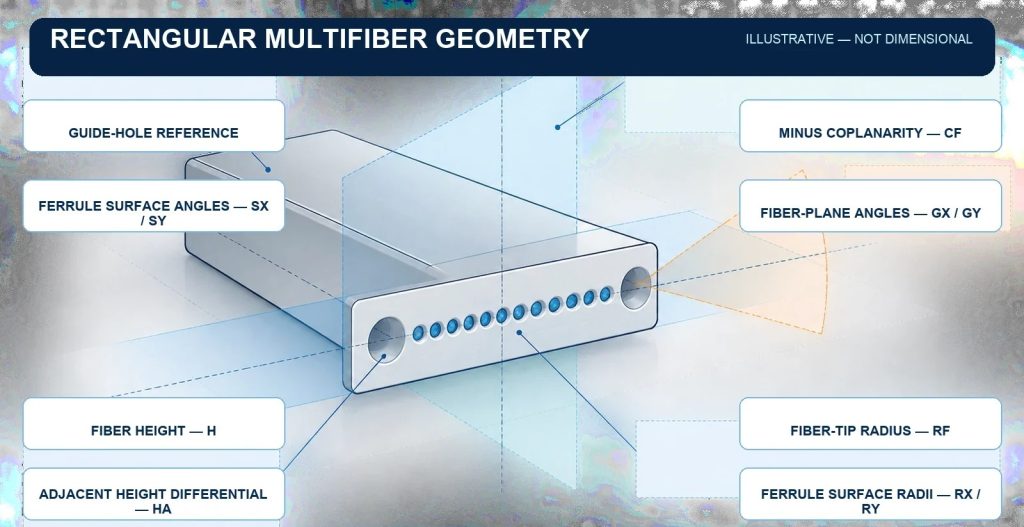
An MPO geometry report may include the following field families. The applicable acceptance values must come from the approved interface document or project specification, not from a generic blog table.
What should an MPO geometry report include?
| Field family | Decision meaning | Review question |
|---|---|---|
| Ferrule surface angles, often reported as SX and SY | Orientation of the fitted ferrule surface relative to the guide-hole reference | Was the correct connector orientation and sign convention used? |
| Fiber height, H | Position of each fiber end relative to the fitted ferrule surface | Are all measured positions evaluated against the applicable interface requirement? |
| Adjacent fiber height differential, HA | Local height difference between neighboring fibers | Does the report include every relevant fiber and the correct neighbor definition? |
| Fiber-array minus coplanarity, CF | The largest negative deviation from the fitted fiber line or plane | Is the array layout and row count represented correctly? |
| Fiber-plane angles, GX/GY | Tilt of the fitted fiber line or plane relative to the guide-hole reference | Are these fields required and reported for this ferrule arrangement? |
| Fiber-tip spherical radius, RF | Fitted curvature of an individual fiber tip | Is the measured region and analysis method stated? |
| Ferrule surface radii, RX/RY | Curvature of the fitted rectangular ferrule surface along two axes | Do not replace these with the single-fiber “radius of curvature/apex offset” shorthand. |
| Geometry limit, GL | A calculated merit value used by the method for supported configurations | Is the correct fiber-count table and method edition used? |
| Core dip | Core elevation relative to surrounding cladding for multimode fibers | Is this field applicable to the fiber type and measured with the stated method? |
Radius of curvature, apex offset and fiber height are not a complete reporting model for a guide-pin-based rectangular multifiber ferrule. The first two labels are common in single-fiber connector reports. For MPO acceptance, ask for the actual rectangular-ferrule fields and the requirement applied to each field.
Geometry is normally measured in a controlled production or qualification environment with a 3D interferometry analyzer and an appropriate fixture. A field video microscope is not a substitute for that geometry measurement.
Which instrument answers which MPO acceptance question?
| Instrument category | Primary decision | Typical record | It cannot prove by itself |
|---|---|---|---|
| Visual inspection probe or microscope with an MPO tip/fixture | Whether visible contamination, scratches and defects meet the approved inspection plan | Full-ferrule and required position-level images or analyzed results | Three-dimensional ferrule geometry, IL/RL or polarity |
| 3D interferometry analyzer with the approved rectangular-ferrule fixture | Whether measured ferrule and fiber geometry fields meet the applicable interface/project requirement | Field-level geometry values, limits and overall evaluation for the identified end | Shipment cleanliness, optical loss or fiber map |
| OLTS or approved insertion-loss/return-loss setup | Whether the stated optical path meets its loss/reflectance requirement under the defined reference method | Wavelength-, direction- and path-specific IL/RL results | End-face geometry or end-to-end fiber mapping |
| Polarity or continuity mapper | Whether fiber positions follow the controlled channel map | Position-to-position mapping and overall map result | Cleanliness, geometry or optical margin |
Select the instrument from the acceptance question, not from a generic claim that one tester is an “all-in-one” solution. If a platform combines functions, its report must still preserve the method, limits, result and traceability for each evidence layer.
If the project requirement names a result but not the correct record, ask BWNFiber to review the evidence request before the RFQ is finalized. Include the drawing revision, approval milestone and the report titles already specified; the review should identify missing fields without inventing a new acceptance limit.
Review the visual-inspection record
IEC 61300-3-35:2022 covers observation and classification of debris, scratches and defects on connector end faces. Its public summary makes three points that matter for MPO acceptance:
- Visual inspection supplements rather than replaces attenuation, return-loss or end-face-parameter measurement.
- For a rectangular ferrule, cleanliness inspection includes the whole ferrule surface, not only a quick look at the center fibers.
- Quantitative image analysis depends on the connector/interface category and the approved criteria. A generic “Zone A is absolute” sentence is not a safe substitute for the current licensed document.
The 2022 edition’s published change summary says that the prior Zone C and D inspection requirements were removed. A fixed four-zone A/B/C/D tutorial should therefore not control an acceptance decision.
The same IEC change summary states that a connector cannot be rejected solely because it fails visual inspection; the specified optical performance determines its use. This does not turn a contaminated or damaged interface into an automatic release. Record the visual result, apply the approved clean, reinspect or engineering-disposition step, and keep the final decision tied to the buyer’s controlled plan.
What should an MPO visual-inspection report include?
An auditable MPO visual-inspection record should identify:
- the part, unit/lot and end being inspected;
- the connector configuration and fiber-position convention;
- the standard or customer procedure and exact edition;
- the inspection-system model, tip/fixture and software/analysis version where controlled;
- the full-ferrule cleanliness view required by the plan;
- the relevant per-fiber images or machine-readable result;
- the criteria applied and the result per required position;
- cleaning, reinspection, exception, rework and final-disposition history;
- the date and authorized reviewer or release role.
Do not reduce this to “200x/400x microscope, no defects in Zone A.” The inspection system must meet the selected method and resolve the features that the plan requires. The approved procedure and current standard control the decision.
The fiber cleaning guide covers the clean-and-reinspect procedure. The acceptance record should capture the initial condition, cleaning action, reinspection result and final disposition.
Separate factory evidence from receiving condition
A report created before packing describes the connector at that process stage. It cannot establish the surface condition after transport, storage, protective-cap handling or site staging. If receiving condition is part of release, define when the interface must be inspected again, who may remove the cap, and how the new result is linked to the correct assembly and connector end.
Connect end-face evidence to optical and polarity records

After geometry and visual condition are reviewed, the release packet still needs the other records required by the project.
For IL or RL, the report should name the measured path, direction where relevant, wavelength, reference method/setup, test equipment state, limit, result and unit identity. A single number without those conditions cannot be compared safely with a quotation, another supplier or an installed-link result.
For polarity, the record should identify the approved end-to-end map, viewing convention, connector keys and genders, intermediate components where applicable, and the measured position-to-position result. “Type B” alone is not a complete channel map.
The general fiber testing guide explains the broader distinction among inspection, OLTS and OTDR. The MPO trunk installation guide covers routing, mating and post-installation commissioning.
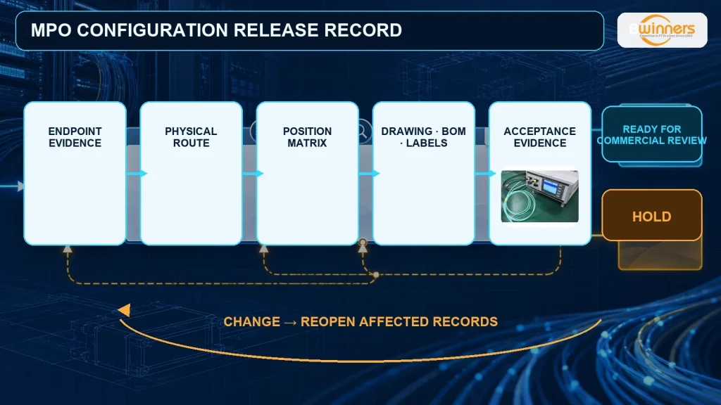
Build one release index
Use one row per unit or controlled sample so that report IDs cannot drift away from the assembly they cover:
| Identity | Configuration revision | Geometry record | Visual record | IL/RL record | Polarity record | Exceptions | Release decision |
|---|---|---|---|---|---|---|---|
| Unit/lot ID | Drawing/BOM rev | Report ID + status | Report ID + status | Report ID + status | Report ID + status | NCR/deviation ID | Release / conditional / hold / reject |
The index does not replace the reports. It lets the reviewer confirm that every record covers the same configuration and identified scope.
Six steps to build an MPO acceptance plan
- Freeze the exact MPO configuration, drawing revision, mating interface and evidence scope.
- Name the applicable method, document edition and configuration-specific requirement for each record.
- Define unit-, lot- or controlled-sample traceability before the supplier tests the assembly.
- Review geometry, visual condition, IL/RL and polarity as separate evidence layers.
- Link every required record, exception and retest to one release index.
- Release, conditionally release, hold or reject only through the buyer-approved quality plan.
Use this sequence in an RFQ, first-article inspection or incoming-quality plan. The licensed standards and the buyer’s controlled acceptance procedure still govern the decision.
Minimum fields for an auditable supplier report
A useful report lets a second reviewer reconstruct the decision without asking what “PASS” meant. Require these field groups:
- Identity: supplier legal entity/site where relevant, work order, lot, unit/serial, connector end and report ID.
- Configuration: product/drawing/BOM revision, fiber count/row, fiber mode, interface/polish, pin state where relevant and mating reference.
- Requirement: document number and edition, project/customer limit, approved deviations and effective revision.
- Method: inspection or measurement procedure, setup, orientation, conditions and software version where controlled.
- Equipment state: instrument/fixture ID and calibration or verification status required by the quality plan.
- Results: raw or summarized values, images, position-level result and overall evaluation without hiding failed positions in an average.
- History: initial result, cleaning or rework authorization, retest/reinspection result and retained links to nonconformance records.
- Disposition: the named role, decision, date, scope and any conditions on release.
Connector records are one input to the broader MPO supplier qualification process. The supplier file should also cover the legal entity, manufacturing site, controlled process, pilot approval and change control.
Match report scope to the release decision
Do not request every record at unit level by habit. The buyer’s risk plan should define whether a report covers a qualification sample, first article, production lot or individual assembly. State the scope in the RFQ because unit-level measurement, retained images and custom data formats can affect inspection time, document handling and the quotation.
| Decision point | Scope to define | Question for the supplier |
|---|---|---|
| Qualification or design approval | Controlled sample or first article | Does the report identify the exact drawing revision and approved configuration? |
| Production release | Lot or unit, as required by the quality plan | How is each result linked to the shipped lot or assembly? |
| Process or configuration change | New review, requalification or documented carry-over | Which changes trigger new evidence, and who approves continued use of earlier records? |
A report for an earlier drawing, polishing process, ferrule type or manufacturing site should not be carried forward without the change-control decision required by the buyer’s plan.
For cross-border orders, state the required report language, units, file format, retention or access period, and contractual standards with their editions. A country or region name by itself does not define an MPO acceptance method.
Five-question evidence sufficiency gate

Before an MPO evidence packet reaches release review, answer these five questions in order. A “no” does not automatically reject the product; it means the packet is not yet sufficient for the requested decision.
| Gate question | If the answer is no | Controlled action |
|---|---|---|
| Do all records identify the same part or drawing revision, connector end, and unit, lot or controlled sample? | The evidence may belong to a different scope | Hold the review and reconcile traceability before comparing results |
| Does the reported configuration match the ordered fiber count and row, fiber mode, interface/polish, pin state and mating reference? | The cited method or limit may not apply | Confirm the configuration and reselect the applicable requirements |
| Does each result name the method and edition, applicable project limit, and required equipment or fixture state? | “Pass” cannot be audited against the contract | Obtain the controlled procedure, limit and equipment-status fields |
| Are all evidence layers required by the quality plan present: geometry, visual condition, IL/RL and polarity? | An open acceptance question remains | Request the missing record; do not let one evidence type substitute for another |
| Are failures, cleaning, rework, retest, deviations and final disposition linked to the affected scope? | The current status is ambiguous | Keep the scope on hold until the history and authorized decision are traceable |
Only a packet that clears all five gates is eligible for the buyer’s authorized disposition. Clearing the gate is not an automatic product release; sampling, limits and approval authority still come from the buyer-approved quality plan.
Disposition workflow when a result fails or is incomplete
| Finding | Immediate state | Controlled next step | Do not use as a shortcut |
|---|---|---|---|
| Removable contamination is found | Do not mate/release the affected interface | Clean with the approved method, reinspect and retain the final result required by the plan | A clean geometry report from an earlier process step |
| A scratch, pit or persistent feature remains | Hold the affected scope pending evaluation | Apply the current inspection criteria and project disposition rule; add optical/engineering review where required | “It looks small” or a sales approval |
| Geometry is outside the approved requirement | Hold the identified unit/lot scope | Review setup validity, then authorize factory rework/retermination and remeasurement under the quality plan | Field cleaning or a passing microscope image |
| IL/RL fails | Hold the measured path | Verify method/setup/reference cords, inspect/clean as applicable, troubleshoot and retest under the approved plan | A visual pass or polarity pass |
| Polarity/map fails | Hold the identified assembly/channel scope | Compare with the controlled map, correct only through an authorized process and retest | A low insertion-loss result |
| Report is untraceable or omits method/limits | Evidence incomplete; release decision stays open | Obtain a corrected, identified record or perform the approved verification | A generic certificate, screenshot or “100% tested” statement |
The buyer’s approved quality plan must define reject, rework, sampling and escalation rules. Do not apply a universal accept/reject threshold across different MPO configurations.
Compare supplier evidence, price and lead time on the same scope
A lower quoted price or shorter lead time is not directly comparable if one offer includes only a lot-level visual summary and another includes qualification, per-unit geometry, IL/RL, polarity, retained images or custom report formatting. Normalize the assembly and evidence scope before comparing suppliers.
| Comparison field | What every supplier should state | Procurement decision it supports |
|---|---|---|
| Assembly configuration | Part/drawing revision, fiber count and row, mode, interface/polish, pin state, mating reference and approved substitutions | Confirms that quotations describe the same assembly |
| Evidence coverage | Geometry, visual condition, IL, RL and polarity status for the requested configuration | Shows which acceptance questions remain open |
| Report granularity | Qualification sample, first article, lot-level or unit-level; retained image/raw-data scope | Makes evidence cost and traceability comparable |
| Method and requirement | Procedure or standard edition, project limit, equipment/fixture state and deviation status | Shows whether a stated PASS can be audited against the contract |
| Exceptions and retest | Cleaning, rework, nonconformance, retest and authorization workflow | Shows how failures will be controlled rather than hidden |
| Data delivery | Language, units, file format, naming convention and retention/access period | Confirms that the buyer can receive and use the records |
| Commercial scope | Sample or first-article availability, MOQ where applicable, evidence/document charges, production lead time and conditions | Prevents price and schedule comparisons from mixing different deliverables |
Ask suppliers to separate the base assembly, qualification or sample work, recurring production evidence and custom document handling where those items affect the offer. Do not infer sample availability, MOQ, lead time or report scope from a generic website statement; obtain configuration-specific written confirmation.
Before moving to an order or project discussion, close four items: the controlled configuration, approved deviations, commercial scope and evidence status. An unresolved field should remain TBC rather than being converted into an assumption.
Resolve buyer objections before release
| Buyer objection | What the buyer is really protecting | Evidence-based answer | Evidence to request | Next action |
|---|---|---|---|---|
| “Why not accept the lowest-priced offer with a PASS report?” | Comparable scope and total approval effort | A price is not comparable until the assembly, report granularity, test scope, retained data and exception handling match. | Quotation breakdown, configuration revision and record-status matrix | Normalize all offers against one evidence baseline before commercial selection. |
| “Why freeze the configuration before selecting a test or limit?” | Avoiding approval against the wrong interface | Fiber arrangement, mode, polish, ferrule/interface and mating reference determine which requirement and fixture are relevant. | Controlled drawing/BOM, mating reference and project specification | Hold the evidence review until the configuration is identified. |
| “Why ask for a sample or first article?” | Finding specification and documentation mismatches before volume release | A sample or first article is useful when the quality plan requires confirmation of the ordered configuration, report format or process evidence. It is not automatically required for every order. | Approved sample/first-article plan, drawing revision, report list and disposition | Ask the supplier to mark availability, timing, scope and approval owner in writing. |
| “Why request IL/RL when the end face passed inspection?” | Preventing a visual result from substituting for optical performance | Inspection evaluates visible surface condition. It cannot establish insertion loss or return loss for the stated path and reference method. | Wavelength-, direction-, path-, method- and limit-specific IL/RL record | Keep the optical decision open until the required record is reviewed. |
| “Why do MOQ and lead time change with the evidence request?” | Budget and schedule certainty | Unit-level measurements, retained images, custom formats, sample approval and deviation review can change production and document handling. Exact effects are supplier- and configuration-specific. | Dated written quotation separating base assembly, approval work, recurring evidence and custom documentation | Confirm MOQ, lead time and validity only after the evidence scope is frozen. |
| “What changes in an OEM/ODM or custom configuration?” | Control of ownership, revisions and substitutions | Custom labels, drawings, interfaces, evidence formats and approval rights add controlled fields and change triggers. They do not prove that every requested option is available. | Drawing ownership, revision control, approved substitutions, labeling/packing files and report responsibilities | Obtain product-, quality- and commercial-owner confirmation before release. |
| “How do we reduce batch-order mismatch?” | Preventing a previously approved sample from drifting away from production | Link the approved configuration, current revision, lot/unit traceability, exceptions, retests and release authority in one index. Define which changes trigger re-review. | Release index, change record, nonconformance/deviation links and written disposition | Block shipment or receipt approval while identity or change status is unresolved. |
If the supplier cannot state which records are available for the exact configuration, the safest CTA is not “request a quote.” It is: send the controlled configuration and evidence list for a document-gap review.
International MPO evidence requirements: localize the contract, not the geometry
The destination market does not create a universal MPO geometry limit or visual-inspection rule. For international procurement, localize the document package, approval path and transport/receiving controls while keeping the applicable interface requirement and buyer-approved quality plan explicit.
| Market or project context | Confirm in the RFQ or contract | Do not assume |
|---|---|---|
| North America | Customer or project specifications; cited TIA, IEC or owner documents and editions; units; NRTL or other certification evidence only when the supplied assembly and project require it | That a TIA reference replaces the applicable MPO interface or IEC measurement requirement |
| Europe | Applicable IEC, EN, customer and tender documents; language; units; material or regulatory declarations required for the actual product and use | That CE, CPR, RoHS or REACH documentation is automatically applicable or available for every assembly |
| Middle East | Consultant/owner submittal format; approval sequence; language; transport/storage and dust/temperature controls that affect packaging, cap handling or receiving inspection | That regional climate changes the end-face geometry acceptance method |
| Southeast Asia | Project specifications; language and units; humidity/transport/storage controls; import documents; local receiving and approval responsibilities | That one country’s procurement or certification practice applies across the region |
| Latin America | Spanish or Portuguese documentation where required; units; import/packing documents; delivery terms; remote approval and record-access needs | That translated reports can omit the controlling document number, edition or original measured values |
| Africa ISP/FTTH projects | Confirm that MPO assemblies are actually in scope; owner/EPC specifications; receiving-site conditions; language, record access, packing and approval milestones | That a broad ISP/FTTH project automatically needs this data-center MPO evidence package |
Climate and installation method matter when they change the assembly specification, packaging, storage, handling or receiving plan. They should be captured in the controlled product/RFQ documents; they should not be used to invent new geometry limits. Likewise, OEM/ODM, bulk quantity, export packing, certificates, samples and lead time remain configuration- and contract-specific items that require written supplier confirmation.
For cross-border review, request one document index that identifies the controlling language, units, report format, revision, access/retention period, shipment or lot reference, exception history and approval authority. If a translated summary differs from the controlled source record, the contract should state which version governs.
Copy-ready RFQ or first-article evidence clause
Use the following as a controlled starting point, then replace every bracketed field:
For assembly
[part number / drawing revision], configuration[fiber count and row / mode / interface and polish / pin state / mating reference], provide the evidence required by the approved test plan:[geometry / visual inspection / IL / RL / polarity]. Each report shall identify the unit or controlled sample, connector end, method and document edition, applicable project limit, equipment/fixture identification and required status, measured results, exceptions, rework/retest history and authorized disposition. Geometry measurement shall use the approved rectangular-multifiber method and applicable interface requirement. Visual inspection shall use the approved IEC 61300-3-35:2022 plan and shall not be presented as a substitute for optical, geometry or polarity evidence. No substitution of method, limit, site, configuration or report scope is allowed without written approval by[owner].
Ask the supplier to mark each requested record as available, sample-only, lot-level, unit-level, pending, access-controlled or unavailable. That is more useful than asking whether the product is simply “IEC compliant.”
BWNFiber recommends sending one configuration-and-evidence brief instead of separating the request across several emails. Include the configuration fields above, requested quantity and timing, the standards/editions named by the project, required evidence level, sample or first-article need, file/retention requirements and approval milestone.
BWNFiber’s exact report, sample, customization, MOQ, price and lead-time availability must be confirmed for the quoted configuration. The technical response should identify what is available, what requires product or quality-owner confirmation, what remains TBC, and what is outside the offer. This is the brand promise the page can support: a transparent evidence-gap response, not a universal claim that every test or document is available for every assembly.
Primary next step: Send the MPO configuration and evidence requirements for a document-gap review. After the configuration and evidence scope are confirmed, request the applicable sample/first-article plan and commercial quotation.
FAQ
What does MPO end-face inspection prove?
It can document visible debris, scratches and defects within the approved inspection scope. It does not, by itself, prove geometry, insertion loss, return loss or polarity.
Is MPO end-face geometry the same as cleanliness inspection?
No. Geometry is a three-dimensional measurement of the rectangular ferrule and fiber positions. Cleanliness/visual inspection evaluates visible contamination and surface features. They use different methods and answer different acceptance questions.
Which standard covers MPO rectangular-ferrule geometry measurement?
IEC 61300-3-30:2026 describes the measurement method for rectangular multifiber ferrule end-face geometry. The applicable interface requirements and project limits must also be identified.
Is IEC 61755-3-31 a universal MPO geometry specification?
No. IEC 61755-3-31:2015 has a defined scope for an angled PPS rectangular ferrule interface using non-dispersion-shifted single-mode physically contacting fibers. Confirm that scope matches the assembly before applying its limits.
What should an MPO interferometer report include?
At minimum, it should identify the unit/end and configuration, method and edition, equipment/fixture state required by the plan, applicable limits, measured fields, exceptions, rework/retest history and final disposition.
Can a connector pass visual inspection and still fail optical testing?
Yes. Visual condition, geometry, optical measurements and polarity are separate evidence layers. A visually acceptable interface can still fail an IL/RL requirement, and a low-loss assembly can still have the wrong fiber map.
Can a field microscope measure MPO geometry?
Not as a substitute for the specified 3D rectangular-ferrule geometry method. A field inspection probe is used for visual end-face assessment under its approved procedure; geometry normally requires a suitable interferometry analyzer and fixture.
Do I need an image for every fiber position?
The required image and result scope depends on the approved inspection plan, connector category, risk and contract. State whether the supplier must retain full-ferrule views, per-fiber images, machine-readable analysis or a traceable summary.
Can cleaning fix a geometry failure?
No. Cleaning can remove contamination. It does not correct ferrule surface angles, fiber height relationships, coplanarity or other geometry fields. Geometry nonconformance needs controlled factory evaluation and, if authorized, rework or retermination.
What should I send BWNFiber for an evidence review?
Send the part/drawing revision, fiber count/row, fiber mode, interface/polish, pin state and mating reference; the required standards and editions; the requested geometry, visual, IL/RL and polarity records; unit/lot traceability level; project limits; and the approval milestone.
What is the difference between MPO endface inspection and interferometry?
Visual inspection classifies visible contamination, scratches and defects under the approved inspection plan. Interferometry measures three-dimensional rectangular-ferrule and fiber-position geometry. Neither result substitutes for the other, and both need configuration-specific requirements and traceability.
Why can an MPO connector pass inspection but still have high insertion loss?
A visual pass only addresses the inspected surface condition. High insertion loss can still arise from geometry, mating, alignment, test-reference, fiber-path or other assembly conditions. Keep the path on hold until the approved optical test is verified and the cause is resolved.
Standards and related guides
- IEC 61300-3-30:2026: rectangular multifiber ferrule end-face geometry measurement
- IEC 61300-3-35:2022: visual inspection of fiber-optic connector end faces
- IEC 61755-3-31:2015: scoped angled PPS rectangular ferrule interface requirements
- IEC 61754-7-1:2014: one-row MPO family interface dimensions
- MPO supplier qualification checklist
- Pre-terminated MPO deployment guide
- MPO trunk installation guide
Technical notice: This guide is for reference only. It is not an IEC substitute, product certificate or performance guarantee. The applicable licensed standards, buyer-approved quality plan and configuration-specific records govern methods, limits, sampling and report availability.