BWN-PLC-MMST-1X2-NA-0.25-U7525
Bare Fiber PLC Splitter
BWN-PLC-MMST 1×2 Unequal 75/25 Bare Fiber PLC Splitter
Proposed model: BWN-PLC-MMST-1X2-NA-0.25-U7525 Configuration: 1 input × 2 outputs, nominal 75% / 25% split Lead format: 250 µm, unterminated — TBC — model drawing and BOM required Primary next step: Request the model datasheet, port map, test record, and quotation.

Proposed model: BWN-PLC-MMST-1X2-NA-0.25-U7525
Configuration: 1 input × 2 outputs, nominal 75% / 25% split
Lead format: 250 µm, unterminated — TBC — model drawing and BOM required
Primary next step: Request the model datasheet, port map, test record, and quotation.
This proposed 1×2 unequal bare PLC splitter is intended for protected integration where one optical input must be divided into two unequal paths. The supplied serialized test sheet identifies a 75% path and a 25% path, G.657A1 fiber, no connectors, a 40 × 4 × 4 mm package, and three-wavelength measurements for one photographed unit. Before design release, match the physical leads to the approved port map and confirm every model-level limit on the controlled datasheet.
Key Configuration
| Field | Proposed / observed value | Release status |
|---|---|---|
| BWNFiber model | BWN-PLC-MMST-1X2-NA-0.25-U7525 | TBC — approved SKU-to-P/N cross-reference required |
| Factory P/N shown on test sheet | 1×2-0.25-1.0M | Observed for S/N 25120100004 |
| Input / outputs | 1 × 2 | Observed for photographed unit |
| Nominal split | 75% / 25% | Observed; ratio convention and physical port map TBC |
| Fiber | G.657A1 | Observed; model/order scope TBC |
| Lead diameter | 250 µm | TBC — controlled drawing/BOM required |
| Connector | None / N/A | Observed for photographed unit |
| Lead length | ≥1.0 m | Observed for photographed unit; order tolerance TBC |
| Package | 40 × 4 × 4 mm | Observed; use a controlled drawing for host fit |
| Operating wavelength | 1260–1650 nm | Observed on serialized test sheet |
| Operating/storage temperature | −40 °C to +85 °C | Observed on serialized test sheet; qualification basis TBC |
Optical Limits Shown on the Supplied Serialized Test Sheet
| Parameter | 75% row | 25% row | Evidence boundary |
|---|---|---|---|
| Insertion loss, maximum | 2.00 dB | 7.20 dB | Shown on the supplied sheet; approve model-level limits before publication |
| PDL, maximum | 0.20 dB | 0.20 dB | Same boundary |
| Return loss | >55 dB | >55 dB | Same boundary |
| Directivity | >55 dB | >55 dB | Same boundary |
Do not calculate a route budget from the nominal 75/25 percentages alone. Use the approved maximum input-to-output loss for each identified physical path, then add every connector, splice, fiber segment, passive element, design allowance, and required operating condition.
Serialized Measurement Example
S/N: 25120100004
Inspection date shown: 2025/12/1
Connector state: N/A / unterminated
| Test-sheet row | IL @1310 nm | IL @1490 nm | IL @1550 nm | PDL @1310 nm | PDL @1490 nm | PDL @1550 nm | RL |
|---|---|---|---|---|---|---|---|
| Port 75% | 1.84 dB | 1.71 dB | 1.70 dB | 0.07 dB | 0.07 dB | 0.08 dB | Pass >55 dB |
| Port 25% | 7.01 dB | 6.99 dB | 6.99 dB | 0.02 dB | 0.03 dB | 0.07 dB | Pass >55 dB |
Measured values vary by unit. Approve the project against the current model limits and use the test record for the serial number supplied to the order.
Confirm the Port Map Before Design Release
The labels 75% and 25% identify nominal optical distribution, but they do not, by themselves, prove which physical lead is the continuing path or the local branch in your design. Require a controlled drawing that maps:
- common input;
- physical 75% output;
- physical 25% output;
- lead colors or labels;
- fiber-exit direction;
- drawing and product revision.
If the approved topology uses the 75% output as a continuing path and the 25% output as a local branch, record that project assignment in the route matrix and field labels. Do not infer it from draft marketing text.
Host and Application Conditions
Use this compact unterminated component only inside a host assembly that provides the required fixation, fiber routing, transition protection, bend control, service slack, splice storage, cover clearance, and environmental protection. The project owner must approve the topology, optical budget, host enclosure, installation method, and acceptance criteria.
Potential fit includes protected splice trays, optical distribution modules, closures, or custom assemblies when the approved drawing and budget match. The product name alone does not establish GPON, XGS-PON, outdoor, or operator-specific compatibility.
For broader package selection, compare bare fiber PLC splitter packages. If the network architecture is still open, use the fiber splitter selection guide. For an approved unequal route, follow the unbalanced tap-chain design and acceptance guide and calculate the complete optical path budget. Those pages own family selection and network design; this page remains limited to the exact product configuration.
How to Specify This Configuration
Before comparing a quotation with the design, confirm:
- exact BWNFiber SKU and factory P/N mapping;
- 1×2 ratio convention and physical port identities;
- controlled package drawing and available host clearance;
- fiber grade, lead diameter, input/output lengths, labels, and exit direction;
- approved maximum and minimum path-loss requirements by wavelength and direction;
- test method, acceptance revision, and serial-level report format;
- quantity, packaging, target schedule, and any project document requirements.
What to Include in the RFQ
- model or reference configuration;
- required 75%/25% port assignment;
- topology drawing and the role of each output;
- maximum/minimum optical loss window for each route;
- host tray/enclosure drawing and fixation method;
- fiber construction, lead lengths, labels, and termination;
- wavelength/direction cases and test-document requirements;
- quantity, packaging, destination, and target schedule.
Primary CTA: Send the topology, host drawing, optical budget, quantity, and required test documents for a model-matched quotation.
Secondary CTA: Request the controlled datasheet, dimensional/port-map drawing, and a redacted sample test-report format.
Downloads
- Model datasheet:
TBC — source required - Dimensional and port-map drawing:
TBC — source required - Test method / acceptance revision:
TBC — source required - Redacted serial-level test report:
TBC — rights and compliance approval required
FAQ
BWN-PLC-MMST 1×2 Unequal 75/25 Bare Fiber PLC Splitter FAQ
What does 75/25 mean on this 1×2 splitter?
It is the nominal optical distribution between the two outputs. Use the approved model limits—not the percentages alone—for the route budget, and use the controlled drawing to identify the physical 75% and 25% leads.
Is the 75% lead automatically the through port?
Not without an approved port map and project assignment. The topology, drawing, field labels, and acceptance records must use the same physical-port identity.
Does this unit include connectors?
The supplied serialized test sheet lists connector type as N/A, and the supplied photos show unterminated leads. Confirm the order drawing and BOM for the model being quoted.
Can the photographed measurements be used as contractual model limits?
No. They are a serialized example for S/N 25120100004. Contractual acceptance should reference the approved model datasheet, order requirements, test method, and the report for the delivered serial number.
What must be checked before installing a 250 µm bare-lead splitter?
Confirm host fixation, transition protection, bend control, service slack, splice storage, cover clearance, environmental protection, port labels, and the complete route budget.
Can this page approve a GPON or XGS-PON design?
No. A network owner or qualified designer must approve the topology, optical classes, wavelength plan, route calculations, equipment limits, margins, and acceptance requirements.
Related Products
Related Products
Explore additional fiber optic products related to this item and suitable for similar network deployment needs.

Cassette PLC Splitter
1×9 80/20 Uneven PLC Splitter, SC/APC, 3.0 mm × 3 m ABS Module

Cassette PLC Splitter
1×9 75/25 Unbalanced PLC Splitter with SC/APC and 3 m Leads
Cassette PLC Splitter
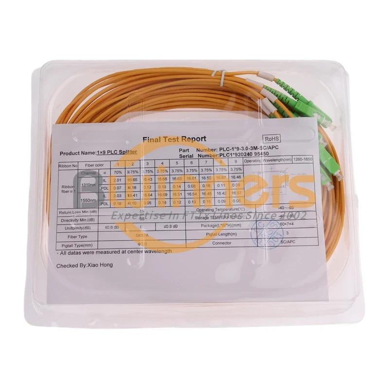
1×9 70/30 Unbalanced PLC Splitter, SC/APC, ABS Cassette, 3 m

Cassette PLC Splitter