BWNF-PLC-ABS-1×9-80-20-SCAPC-3M
Cassette PLC Splitter
1×9 80/20 Uneven PLC Splitter, SC/APC, 3.0 mm × 3 m ABS Module
This 1×9 uneven PLC splitter is identified in the supplied product record as an ABS-module build with SC/APC connectors and 3.0 mm, 3 m pigtails. Its port plan is 80/2.5×8 : one high-power output carries the nominal 80% branch, while eight local outputs each receive a nominal 2.5% share. Use the exact port labels and the approved optical budget; do not treat it as an even 1×9 splitter.

Product value summary
This 1×9 uneven PLC splitter is identified in the supplied product record as an ABS-module build with SC/APC connectors and 3.0 mm, 3 m pigtails. Its port plan is 80/2.5×8: one high-power output carries the nominal 80% branch, while eight local outputs each receive a nominal 2.5% share. Use the exact port labels and the approved optical budget; do not treat it as an even 1×9 splitter.
The supplied final-test-report photograph is tied to serial number 2024095449 and is dated 2024-09-28. Its measured insertion-loss and PDL values describe that serialized build, not a universal production guarantee.
Technical-reference notice: Nominal split ratios and sample measured values are for reference only, not a guarantee. Final product limits, link budgets and acceptance criteria must come from the approved order specification, current drawing and applicable unit or lot test record.
Quick Answer
Choose this configuration only when the approved ODN design calls for one 80% onward path plus eight 2.5% local taps, SC/APC interfaces, 3.0 mm pigtails and 3 m routing length inside the selected host enclosure. Before release, confirm the external module drawing, the input and output labels, the loss limit for every route, and the documents that must ship with the order.
Primary CTA — Request an exact-configuration review: send the topology, host-enclosure drawing, required port labels, maximum loss for each route, quantity and document list. BWNFiber should return a reviewed configuration, current dimensional drawing, available test-record format and quotation-specific commercial terms.
Verified configuration
| Field | Draft value | Evidence status |
|---|---|---|
| Commercial SKU | BWNF-PLC-ABS-1×9-80-20-SCAPC-3M | TBC — reconcile with label P/N |
| Label part number | PLC-B-1X9-3.0-3M-SC/APC | Observed on supplied product photo |
| Configuration | 1 input × 9 outputs | Observed on label and test report |
| Uneven split plan | 80/2.5×8 | Observed on label and test report |
| Connector | SC/APC | Observed on label, report and product photos |
| Fiber | G.657A | Observed on test report; subclass not stated |
| Pigtail construction | 3.0 mm | Observed on label and test report |
| Pigtail length | 3 m | Observed on label and test report |
| Operating wavelength | 1260–1650 nm | Observed on test report |
| External ABS-module dimensions | TBC — approved drawing required | The report's 60 × 7 × 4 mm field must not be used as outer housing size |
| Current production optical limits | TBC — current datasheet required | One serial-specific report is supplied |
| Standards/certification | TBC — source required | Do not infer from family pages or marks in a photograph |
Port map and optical-budget use
| Port | Intended role | Nominal split | Design check |
|---|---|---|---|
| IN | Optical input | 100% input reference | Confirm input label and direction on the approved drawing |
| P1 | Cascade / onward path | 80% | Apply the approved maximum loss for the complete route |
| P2–P9 | Eight local taps | 2.5% each | Budget each tap independently; use the worst permitted tap loss |
The ratio label describes nominal power allocation, not insertion loss. The cascade path and the tap paths have different measured losses. Include connectors, splices, fiber length, other splitter stages, equipment limits and engineering margin when closing the installed-route budget. For broader calculation guidance, use the BWNFiber splitter-loss guide rather than expanding this SKU page into a general link-budget article.
See the splitter-loss and link-budget guide for the wider route calculation method and the GPON splitter selection guide for topology-level selection.
Serialized factory test record supplied for review
The following values were transcribed from the supplied final-test-report photograph for serial number 2024095449. They are sample-specific measured results, not published maximum limits for every production unit.
| Port | Role | Nominal split | IL at 1310 nm (dB) | PDL at 1310 nm (dB) | IL at 1550 nm (dB) | PDL at 1550 nm (dB) |
|---|---|---|---|---|---|---|
| P1 | Cascade | 80% | 1.92 | 0.13 | 1.89 | 0.06 |
| P2 | Tap 1 | 2.5% | 16.81 | 0.06 | 16.87 | 0.07 |
| P3 | Tap 2 | 2.5% | 16.79 | 0.08 | 16.66 | 0.08 |
| P4 | Tap 3 | 2.5% | 16.65 | 0.20 | 16.87 | 0.10 |
| P5 | Tap 4 | 2.5% | 16.64 | 0.05 | 16.78 | 0.07 |
| P6 | Tap 5 | 2.5% | 16.82 | 0.06 | 16.61 | 0.07 |
| P7 | Tap 6 | 2.5% | 16.75 | 0.06 | 16.62 | 0.14 |
| P8 | Tap 7 | 2.5% | 16.89 | 0.18 | 16.72 | 0.13 |
| P9 | Tap 8 | 2.5% | 16.65 | 0.12 | 16.71 | 0.19 |
The same photographed report lists return loss of 55 dB minimum, directivity of 55 dB minimum and tap-port uniformity of 0.8 dB maximum. Publish these only in a clearly labeled serial-specific record or after Quality approves current model-level limits and test conditions.
Fit and application conditions
This build may suit a protected PON distribution point where the design requires an onward high-power branch and eight local service taps. System suitability is conditional: the host enclosure must accommodate the actual module, ten connectorized pigtails, the 3 m service length, controlled bends, labeling and access for inspection. The approved ODN budget must also cover every cascade and local path.
Do not use this SKU when:
- the design requires nine equal outputs;
- the host cannot accept the approved external module dimensions or 3.0 mm pigtail routing;
- the required connector polish or port-label scheme differs;
- the link budget was calculated from an even-split 1×9 table;
- the buyer requires a certification, environmental qualification or current production limit that BWNFiber has not documented for this SKU.
Difference from related BWNFiber products
| Product role | Key difference | Correct next step |
|---|---|---|
| Existing BWN-PLC-1X9-80:20 mini page | Its hero specifies 0.9 mm fiber and 1.5 m length; the current page also mixes package-family rows | Treat as a separate mini build or convert it to a governed variant owner before launching this page |
| Uneven 1×5/1×9/1×17 family page | Covers configurable blockless/steel-tube products and several ratios | Use for family discovery, not as evidence for this ABS 3.0 mm × 3 m SKU |
| Cassette PLC splitter category page | Helps buyers select package, split plan, fit and interfaces | Use for category navigation and comparison |
| Splitter selection/loss guides | Own general selection and link-budget education | Link to them; do not duplicate them on this SKU page |
Browse the cassette PLC splitter range for package-level comparison, or review the existing 0.9 mm, 1.5 m mini 1×9 80:20 model before approving the owner/variant relationship.
How to specify the correct configuration
- State the exact commercial SKU and reconcile it with the label part number.
- Confirm
1×9, 80/2.5×8in the drawing and purchase description. - Identify the input, the 80% cascade output and each 2.5% tap by label.
- Confirm SC/APC on every required end and define dust-cap/adapter handling.
- Confirm G.657A subclass, 3.0 mm construction and 3 m length.
- Approve the external housing dimensions, pigtail exits, fixing method and routing clearance.
- Set maximum optical limits and test wavelengths for every port.
- Define the datasheet, drawing, test record, label proof and packing evidence required with the order.
Testing and quality-control record
For procurement approval, request a current model datasheet and define whether the order requires a per-unit, per-lot or sample test record. The record should identify the product/SKU, serial or lot, port map, test wavelengths, IL/PDL fields, acceptance limits, equipment/method reference where required, date and disposition. A factory component report does not prove installed-route acceptance after splicing, adapter mating and field routing.
Packaging and procurement information
The supplied photos show the module and pigtails in a clear plastic tray. Final sales packaging, quantity per carton, label format, dust protection, MOQ, price, stock, lead time and warranty are TBC — quotation or approved packaging specification required.
RFQ information to send
- Exact SKU or the phrase
1×9, 80/2.5×8, ABS module - Network topology and the function of the 80% cascade leg
- Maximum loss for the cascade route and each local route
- Connector type/polish and port-label sequence
- Fiber subclass, pigtail diameter and length
- Host-enclosure drawing and available routing space
- Quantity, destination and requested schedule
- Required datasheet, dimensional drawing, test record, label proof and compliance documents
Download area
- Current datasheet: TBC — source required
- Approved dimensional drawing: TBC — source required
- Model-level optical limits: TBC — source required
- Sample serial-specific test report: available as a supplied image; public-use approval required
- Compliance documents: TBC — source required
FAQ
1×9 80/20 Uneven PLC Splitter, SC/APC, 3.0 mm × 3 m ABS Module FAQ
What does 80/20 mean on this 1×9 splitter?
For the supplied build, the label expands 80/20 as 80/2.5×8: one output is the nominal 80% cascade leg and eight outputs are nominal 2.5% taps. It is not an even 1×9 split.
Are the measured insertion-loss values production guarantees?
No. The table above belongs to one serialized build dated 2024-09-28. Use current, approved maximum limits for procurement and the unit or lot report required by the purchase specification.
Does 60 × 7 × 4 mm describe the external ABS box?
It should not be treated as the outer housing dimension. The photographed ABS housing is visibly larger. Request the approved external dimensional drawing before checking enclosure fit.
Can this page confirm GPON or XGS-PON compatibility?
The reported wavelength range covers common PON wavelengths, but system approval still depends on the complete optical budget, topology, connector interfaces, equipment limits and project acceptance criteria.
What should be verified before placing an order?
Verify the exact SKU/P/N mapping, ratio string, port labels, connector polish, fiber subclass, pigtail construction and length, housing dimensions, optical limits, test-document scope and quotation-specific commercial terms.
Related Products
Related Products
Explore additional fiber optic products related to this item and suitable for similar network deployment needs.

Cassette PLC Splitter
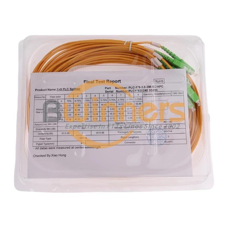
1×9 75/25 Unbalanced PLC Splitter with SC/APC and 3 m Leads
Cassette PLC Splitter
1×9 70/30 Unbalanced PLC Splitter, SC/APC, ABS Cassette, 3 m

Cassette PLC Splitter
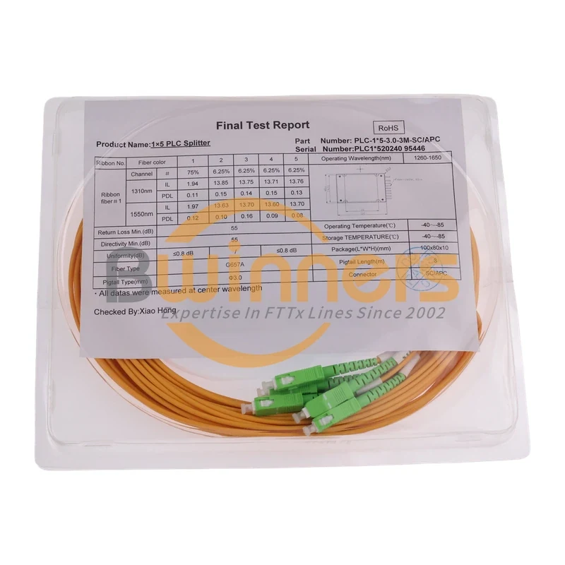
1×5 80/20 Unbalanced PLC Splitter, SC/APC, ABS Module, 3 m
Cassette PLC Splitter