BWNF-PLC-ABS-1×9-75-25-SCAPC-3M
Cassette PLC Splitter
1×9 75/25 Unbalanced PLC Splitter with SC/APC and 3 m Leads
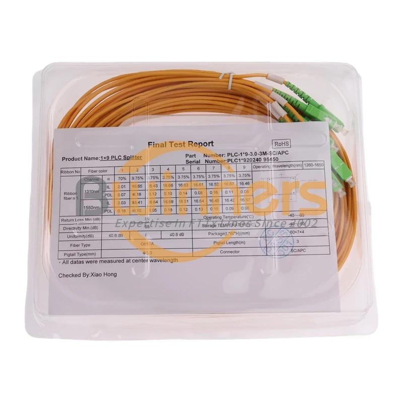
This exact configuration separates one optical input into one nominal 75% route and eight nominal 3.125% routes. The photographed build uses a black ABS housing, SC/APC terminations and 3 m, 3.0 mm G.657A leads. A same-serial sample report records insertion loss and polarization-dependent loss for all nine outputs at 1310 nm and 1550 nm.

5. Product value summary
This exact configuration separates one optical input into one nominal 75% route and eight nominal 3.125% routes. The photographed build uses a black ABS housing, SC/APC terminations and 3 m, 3.0 mm G.657A leads. A same-serial sample report records insertion loss and polarization-dependent loss for all nine outputs at 1310 nm and 1550 nm.
Primary CTA: Request Configuration and Test-Document Review
Provide your topology, required port map, path-loss limits, host-enclosure drawing and quantity. BWNFiber should return a configuration review, an approved model specification and the available drawing/test-document set.
6. Short answer for buyers
The 75/25 label does not mean nine equal outputs. For this build, the label expands the split plan to 75/3.125×8: one high-power output is nominally 75%, while the other eight outputs are nominally 3.125% each. Approve the port identification and the optical budget before installation; do not substitute an equal 1×8 or another 1×9 ratio based on port count alone.
7. Key features
- Exact configuration: 1 input and 9 outputs.
- Nominal port plan: one 75% route plus eight 3.125% routes.
- Observed interface: SC/APC on the input and all nine outputs.
- Observed lead construction: G.657A, 3.0 mm, 3 m.
- Observed package: black ABS outer housing with external pigtails.
- Reported operating wavelength: 1260–1650 nm.
- Traceable sample report: per-port IL and PDL at 1310 nm and 1550 nm.
- Procurement control: confirm the port-label map, host-enclosure fit and production acceptance limits before release.
8. Technical specifications
| Attribute | Evidence-bounded value | Status |
|---|---|---|
| Proposed sellable SKU | BWNF-PLC-ABS-1X9-75-25-SCAPC-3M | Product-owner approval required |
| Factory label P/N | PLC-B-1X9-3.0-3M-SC/APC | Observed on sample label |
| Test-report P/N | PLC-1*9-3.0-3M-SC/APC | Observed on same-serial report |
| Configuration | 1×9 | Supported by label/report |
| Nominal split plan | 75/3.125%×8 | Supported by label/report; port naming to approve |
| Connector | SC/APC | Supported for photographed/tested sample |
| Fiber | G.657A | Do not infer A1 or A2 |
| Lead diameter | 3.0 mm | Supported for sample |
| Lead length | 3 m | Supported for sample |
| Outer housing | Black ABS | Supported by photographs |
| Outer housing dimensions | TBC — approved drawing required | The report's 60×7×4 mm must not be presented as the outer ABS dimensions |
| Operating wavelength | 1260–1650 nm | Reported value |
| Return loss | ≥55 dB | Reported limit; test method not supplied |
| Directivity | ≥55 dB | Reported limit; test method not supplied |
| Tap-port uniformity | ≤0.8 dB | Reported limit for the eight tap outputs |
| Operating temperature | −40°C to +85°C | Reported field; qualification evidence not supplied |
| Storage temperature | −40°C to +85°C | Reported field; qualification evidence not supplied |
| Compliance/certification | TBC — source required | Do not claim Telcordia or RoHS compliance from the current files alone |
9. Port map
| Connection | Nominal role | Nominal share | Approval requirement |
|---|---|---|---|
| Input | Optical input | 100% reference | Confirm input label and route |
| P1 | High-power / continuation route | 75% | Confirm physical label and destination |
| P2–P9 | Eight lower-power routes | 3.125% each | Confirm numbering and service mapping |
The names “continuation route” and “lower-power routes” describe the intended power relationship. The final wiring drawing and field labels must come from the approved project document set.
10. Sample per-port test results
The following values are transcribed from the final test report photographed with serial PLC1*92024095452. They describe that sample only. They are not production acceptance limits and must not replace the current order-specific test report.
| Output | Nominal split | IL at 1310 nm (dB) | PDL at 1310 nm (dB) | IL at 1550 nm (dB) | PDL at 1550 nm (dB) |
|---|---|---|---|---|---|
| P1 | 75% | 1.89 | 0.16 | 1.85 | 0.20 |
| P2 | 3.125% | 16.58 | 0.15 | 16.52 | 0.20 |
| P3 | 3.125% | 16.54 | 0.10 | 16.53 | 0.15 |
| P4 | 3.125% | 16.55 | 0.13 | 16.52 | 0.07 |
| P5 | 3.125% | 16.52 | 0.16 | 16.52 | 0.18 |
| P6 | 3.125% | 16.51 | 0.09 | 16.54 | 0.07 |
| P7 | 3.125% | 16.69 | 0.13 | 16.54 | 0.09 |
| P8 | 3.125% | 16.57 | 0.20 | 16.60 | 0.09 |
| P9 | 3.125% | 16.63 | 0.15 | 16.60 | 0.17 |
For this sample, the highest observed tap IL is 16.69 dB at 1310 nm and 16.60 dB at 1550 nm. Use the approved maximum limit—not this sample's observed value—when closing a project optical budget.
Technical-reference disclaimer: Sample measurements and nominal split percentages are provided for configuration review only. They are not guaranteed production limits. Confirm the approved drawing, specification revision and unit-specific test report before design approval or purchase.
11. Interfaces and connector options
The exact build shown here uses SC/APC throughout. Do not substitute SC/UPC, LC, FC, ST or unterminated fibers without a new approved part number, connector map, loss limit and drawing.
Other interfaces: TBC — approved option matrix required.
12. Fiber type and configuration options
The supplied report identifies the fiber as G.657A; it does not identify A1 or A2. The photographed build uses 3.0 mm leads at 3 m. Other fiber grades, diameters and lengths must be quoted as different approved configurations rather than implied as options of this SKU.
13. Compatibility and application conditions
This unequal split can be considered where a design needs to retain a larger share of optical power on one route while allocating the balance across eight lower-power outputs. Suitability for GPON, XGS-PON or another optical system is conditional on the approved design.
Before approval, verify:
- downstream transmitter and receiver wavelengths;
- loss budget in both directions, including the highest-loss route and any minimum-loss/receiver-overload constraint;
- every connector, splice, fiber segment and engineering margin;
- any additional splitter stages on the continuation route;
- host-enclosure space, bend control and pigtail routing;
- SC/APC mating throughout the interface chain; and
- final port labels against the network node plan.
The ABS module is not presented here as a weatherproof enclosure. Outdoor use requires a separately approved host enclosure and environmental design.
14. How to select the correct model or configuration
- Start with the approved node topology and identify why one route requires a nominal 75% share.
- Calculate the end-to-end budget for the continuation route and each lower-power route.
- Confirm the required connector family and APC polish at every mating point.
- Measure the routing distance inside the host enclosure and approve the 3.0 mm, 3 m leads.
- Verify the outer ABS drawing, mounting method and bend-clearance envelope.
- Approve the part number, port map, production limits and document pack before placing the order.
15. Differences from related BWNFiber products
| Product/page | Key difference | Correct buyer use |
|---|---|---|
| This proposed SKU | 1×9; 75/3.125%×8; ABS; SC/APC; G.657A; 3.0 mm; 3 m | Validate this exact BOM configuration |
| Existing 1×9 80/20 product | Different 80/20 ratio; published mini/900 μm/1.5 m construction | Use only when the approved design calls for 80/20 and that construction |
| Existing 1×5/1×9/1×17 unequal family | Family-level configurable mini/blockless selection; 1×9 example is 70/30 | Compare unequal splitter families, then open an exact model record |
| Cassette PLC splitter category | Broad ABS package selection and enclosure-fit guidance | Browse product families and choose the package class |
16. Use cases and non-fit conditions
Potential fit, subject to engineering approval
- Unequal optical distribution where one path must retain a larger nominal share.
- A connectorized assembly installed inside a host cabinet, distribution box or panel that protects and routes the ABS module and leads.
- Projects that require a traceable, per-port test record for the supplied unit.
Do not use this page as approval when
- the design requires equal outputs;
- the required ratio is 80/20, 70/30 or another value;
- the host interface is UPC or a connector other than SC/APC;
- the enclosure cannot accommodate the approved outer dimensions and 3 m leads;
- the wavelength plan or path budget has not been reviewed; or
- a certification, drawing or production limit is required but not included in the approved order documents.
17. Testing and quality-control evidence
The supplied evidence demonstrates that one sample was recorded per output at 1310 nm and 1550 nm for insertion loss and PDL, with report fields for return loss, directivity, tap-port uniformity, wavelength, temperature, fiber, lead size, length and connector. The test instrument, reference method, uncertainty, acceptance-plan revision and environmental qualification records were not supplied.
For a purchase release, request:
- current product specification with production limits;
- exact port-map and dimensional drawing;
- order-specific or serial-specific test report;
- test method and reference conditions when required by the project; and
- any project-required compliance declaration tied to the current BOM.
18. Packaging and procurement information
The photographs show the sample placed in a clear plastic tray with its test report. This is visual evidence of the photographed sample presentation, not an approved export-packaging specification.
| Procurement field | Status |
|---|---|
| MOQ | TBC — sales approval required |
| Price | TBC — quotation required |
| Stock | TBC — live inventory source required |
| Lead time | TBC — operations approval required |
| Warranty | TBC — approved terms required |
| Export packaging | TBC — packaging specification required |
| Sample availability | TBC — sales approval required |
19. Information required for an RFQ
Send the following as one controlled configuration record:
- proposed SKU and required quantity;
- 1×9 configuration and
75/3.125%×8split plan; - input, high-power output and P2–P9 label sequence;
- SC/APC interfaces on the input and all outputs;
- G.657A requirement and any required subtype;
- 3.0 mm lead construction and 3 m input/output lengths;
- host-enclosure drawing, mounting space and pigtail route;
- operating wavelengths and end-to-end optical-budget limits;
- required production acceptance limits and test-report format;
- dimensional drawing, compliance declaration and packaging documents required; and
- target delivery location and schedule.
20. Datasheet / drawing / test-report download area
- Product datasheet: TBC — approved current revision required
- Outer ABS dimensional drawing: TBC — source required
- Port-map drawing: TBC — source required
- Sample test-report image: available in the supplied source set; publication/redaction approval required
- Order-specific test report: request with the quotation/document pack
FAQ
1×9 75/25 Unbalanced PLC Splitter with SC/APC and 3 m Leads FAQ
What does 75/25 mean on this 1×9 unbalanced PLC splitter?
For the supplied build, the label expands the ratio to 75/3.125×8. One output is nominally 75%; the remaining 25% is divided across eight outputs at a nominal 3.125% each. Confirm the physical port labels on the approved drawing.
Are the insertion-loss values on this page guaranteed for every unit?
No. The detailed values are measurements from sample serial PLC1*92024095452. Use the approved production specification and the report for the shipped unit as the acceptance evidence.
Does 60×7×4 mm describe the black ABS housing?
Not from the supplied evidence. That dimension appears in the test report's package field and may refer to the internal PLC package. The outer ABS dimensions require an approved drawing.
Can this splitter be used in a GPON or XGS-PON route?
Only after the wavelength plan, downstream and upstream loss budgets, receiver limits, additional splitter stages and engineering margin are checked for the specific design. The product label alone does not prove system compatibility.
Can SC/UPC be mated to these SC/APC connectors?
Do not approve a direct UPC-to-APC substitution. Match the connector polish across the splitter, adapters and patching plan, and use the interface specified by the approved BOM.
What should be submitted for a quotation?
Send the ratio and port map, fiber/lead construction, connector plan, host-enclosure drawing, path-loss limits, quantity, delivery target and required document pack. This lets BWNFiber review the exact configuration instead of quoting a generic 1×9 splitter.
Related Products
Related Products
Explore additional fiber optic products related to this item and suitable for similar network deployment needs.

Cassette PLC Splitter
1×9 80/20 Uneven PLC Splitter, SC/APC, 3.0 mm × 3 m ABS Module
Cassette PLC Splitter
1×9 70/30 Unbalanced PLC Splitter, SC/APC, ABS Cassette, 3 m

Cassette PLC Splitter
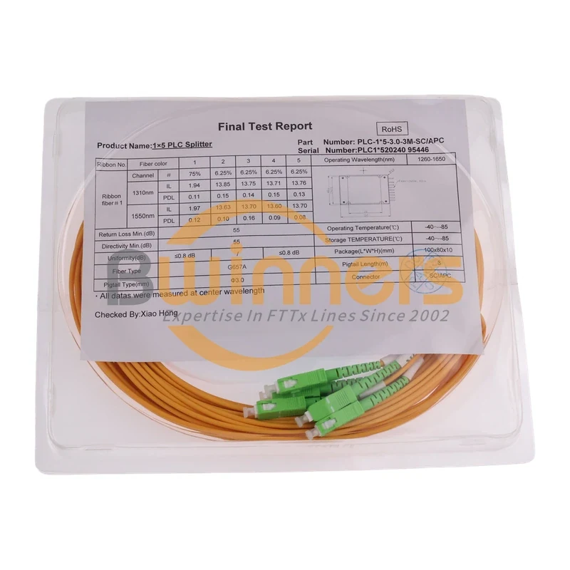
1×5 80/20 Unbalanced PLC Splitter, SC/APC, ABS Module, 3 m
Cassette PLC Splitter