BWNF-PLC-ABS-1×9-70-30-SCAPC-3M
Cassette PLC Splitter
1×9 70/30 Unbalanced PLC Splitter, SC/APC, ABS Cassette, 3 m
This exact configuration is a single-mode 1×9 unequal PLC splitter in a black ABS cassette. One output is labeled as the nominal 70% cascade path; the other eight outputs are labeled as nominal 3.75% service taps. The photographed sample uses SC/APC connectors on 3.0 mm, 3 m pigtails.
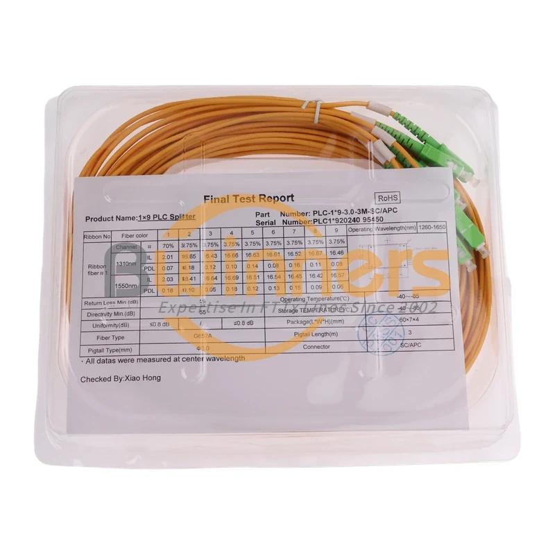
This exact configuration is a single-mode 1×9 unequal PLC splitter in a black ABS cassette. One output is labeled as the nominal 70% cascade path; the other eight outputs are labeled as nominal 3.75% service taps. The photographed sample uses SC/APC connectors on 3.0 mm, 3 m pigtails.
Proposed BWNFiber SKU: BWNF-PLC-ABS-1x9-70-30-SCAPC-3M — TBC: Product Owner approval required
Factory P/N visible on the sample: PLC-B-1X9-3.0-3M-SC/APC
Primary action: Request an exact-configuration review
Send the topology, shortest and longest path budgets, host-enclosure drawing, quantity and required documents. The response scope must be confirmed by BWNFiber Sales/Engineering before this CTA is published.
30-second product summary
Use this page only for the photographed ABS-cassette build: 1 input, 1 nominal 70% cascade output and 8 nominal 3.75% tap outputs, with SC/APC connectors on 3.0 mm, 3 m pigtails. Do not substitute the existing blockless 900 µm / 1.5 m 1×9 model or an equal-split 1×8 device.
Buyer summary
The 70/30 label does not mean two physical outputs. On this 1×9 build, the high-power output receives a nominal 70% share and eight local tap outputs share the remaining nominal 30%, or 3.75% each. The supplied report records IL and PDL for one sample unit at 1310 and 1550 nm. Those readings are serial-specific evidence, not production guarantees. Before quotation or deployment, approve the SKU-to-factory-P/N mapping, housing drawing, maximum acceptance limits, test method, port labels and the link budget for every cascade and subscriber path.
Verified configuration of the supplied sample
| Field | Supplied-sample record | Release status |
|---|---|---|
| Configuration | 1 input × 9 outputs, unequal split | Supported by label/report |
| Nominal split | 70% cascade + 8 × 3.75% taps | Supported by labels/report |
| Package | Black ABS cassette with external pigtails | Supported by photos |
| Connector | SC/APC on the visible pigtails | Supported by photos/report |
| Fiber marking | G657A | Supported by report; A1/A2 subtype not stated |
| Pigtail construction | 3.0 mm, 3 m | Supported by label/report |
| Recorded wavelength range | 1260–1650 nm | Report entry; approve datasheet before treating as a guaranteed limit |
| Recorded temperature range | −40 to +85 °C | Report entry; qualification method not supplied |
| External ABS dimensions | TBC — approved dimensional drawing required | The visible 60×7×4 mm report line may not describe the outer cassette |
| Public BWNFiber SKU | TBC — Product Owner approval required | Proposed only |
| Model-level compliance | TBC — qualification evidence required | Do not claim Telcordia/IEC compliance from family copy |
Port map: what 70/30 means on this 1×9 splitter
| Physical role | Nominal share | Label observed on sample | Design control |
|---|---|---|---|
| Input | 100% input reference | IN | Confirm launch direction and incoming interface |
| Cascade/express output | 70% | 70% | Check the next-node and shortest/longest-path budgets |
| Tap outputs 1–8 | 3.75% each | 3.75% | Check every ONU/branch path independently |
The percentages describe the nominal power division. They are not insertion-loss values and do not replace the maximum model limits used in the optical budget.
Sample-unit IL and PDL record
Source: photographed report for sample S/N 2024095450, dated 2024-09-28. The report says measurements were made at the center wavelength. The full instrument, reference method, calibration, uncertainty, environmental conditions and release limits were not supplied.
| Port | Role | Nominal split | IL 1310 nm (dB) | PDL 1310 nm (dB) | IL 1550 nm (dB) | PDL 1550 nm (dB) |
|---|---|---|---|---|---|---|
| P1 | Cascade | 70% | 2.01 | 0.07 | 2.03 | 0.18 |
| P2 | Tap 1 | 3.75% | 16.65 | 0.18 | 16.41 | 0.10 |
| P3 | Tap 2 | 3.75% | 16.43 | 0.12 | 16.64 | 0.05 |
| P4 | Tap 3 | 3.75% | 16.66 | 0.10 | 16.69 | 0.18 |
| P5 | Tap 4 | 3.75% | 16.63 | 0.14 | 16.51 | 0.12 |
| P6 | Tap 5 | 3.75% | 16.61 | 0.08 | 16.54 | 0.13 |
| P7 | Tap 6 | 3.75% | 16.52 | 0.16 | 16.45 | 0.15 |
| P8 | Tap 7 | 3.75% | 16.67 | 0.11 | 16.42 | 0.09 |
| P9 | Tap 8 | 3.75% | 16.46 | 0.08 | 16.57 | 0.06 |
Technical evidence note: These values describe one supplied sample. Purchase specifications and link budgets must use approved maximum/minimum limits for the ordered revision, not this table alone. Request the current datasheet, drawing, port map and production test-record format before release.
ABS cassette or blockless mini: select the correct BWNFiber record
| Decision field | This proposed page | Existing BWNFiber 1×9 70:30 page |
|---|---|---|
| Package shown | Black ABS cassette with external pigtails | Blockless mini / compact package owner |
| Pigtail construction | 3.0 mm | 900 µm on the published page |
| Length | 3 m | 1.5 m on the published page |
| Termination | SC/APC visible on all supplied pigtails | Published H1 says without connector |
| Correct use | Exact ABS/SC/APC/3 m quotation and verification | Broad blockless 1×9 70:30 selection |
For package-family selection, see the cassette PLC splitter category. For the existing compact alternative, review the blockless 1×9 70:30 PLC splitter.
Application conditions and non-fit cases
This configuration can be evaluated for a cascaded optical-distribution design that requires one higher-power continuation path and eight local taps. Approval still depends on the OLT/ONT or other optical equipment limits, every passive component on each path, the host enclosure, connector interfaces and the project acceptance specification.
Do not use this page as approval for:
- an equal-split 1×8 or 1×9 requirement;
- a blockless, bare-fiber or LGX/insertion package;
- UPC mating interfaces;
- outdoor exposure without an approved host enclosure;
- a GPON/XGS-PON coexistence design without a complete path and wavelength review; or
- guaranteed optical limits derived only from the photographed sample.
For the wider decision process, use the GPON splitter selection and link-budget guide and the PLC splitter product family. Confirm APC versus UPC handling against the approved connector plan; do not mate unlike polish types directly.
How to approve the correct configuration
- Freeze the topology and identify the input, cascade path and all eight tap destinations.
- Calculate the shortest and longest path at every required wavelength using approved maximum component limits.
- Confirm the host enclosure, cassette mounting area, pigtail exit, service slack, bend control and connector access.
- Match the public SKU, factory P/N, drawing revision, port labels and test-record template.
- Define the production acceptance limits, sampling level and exception disposition.
- Release the quotation or purchase order only after technical and commercial revisions agree.
Testing and acceptance documents
Request the records needed by the project rather than assuming a generic family statement applies:
- current exact-model datasheet;
- dimensional drawing and pigtail-exit detail;
- controlled port map and label sequence;
- maximum/minimum optical acceptance limits at the project wavelengths;
- production test-record format and serial/lot traceability;
- connector end-face and cleaning requirement;
- packaging and label specification; and
- model-specific compliance evidence, if the project requires it.
RFQ input checklist
Send the following in one controlled request:
- proposed public SKU or factory P/N;
- required nominal ratio and expanded port map (
70% + 8 × 3.75%); - topology and the role of the cascade output;
- shortest/longest path budgets and equipment limits;
- ABS-cassette space, mounting method and pigtail-exit constraints;
- G657 subtype required, pigtail diameter and input/output lengths;
- SC/APC interface quantity and port-label convention;
- quantity, destination and required schedule;
- required datasheet, drawing, sample and test/compliance records; and
- acceptance limits, sampling rule and failure disposition.
Downloads
- Exact-model datasheet:
TBC — source required - Approved dimensional drawing:
TBC — source required - Sample-unit test report:
TBC — public-release approval required - Production acceptance specification:
TBC — source required
FAQ
1×9 70/30 Unbalanced PLC Splitter, SC/APC, ABS Cassette, 3 m FAQ
What does 70/30 mean on a 1×9 PLC splitter?
On the supplied build, it means one nominal 70% cascade output and eight nominal 3.75% taps. The eight taps together account for the nominal 30% branch share. These percentages are a port map, not insertion-loss guarantees.
Are the values in the test table guaranteed limits?
No. They are readings for the photographed sample S/N 2024095450. Use an approved model datasheet and acceptance specification for design and purchasing limits, then compare the delivered serial or lot record with those limits.
How is the cascade output identified?
The supplied sample shows a 70% label on the high-power output and 3.75% labels on the eight taps. The ordered label sequence and controlled port map must still be approved before production.
Can I replace this unit with BWNFiber’s blockless 1×9 70:30 model?
Not without reviewing package fit, pigtail construction, length, termination and optical limits. The current blockless page lists 900 µm, 1.5 m and no connector in its H1, while this sample is an ABS cassette with 3.0 mm, 3 m, SC/APC pigtails.
What should I submit for a quotation?
Submit the topology, path-budget limits, exact ratio/port map, host-enclosure constraints, fiber and pigtail requirements, connector/polish, quantity, destination, schedule and required technical documents. Ask for the returned quote, datasheet, drawing and test-record scope to reference the same revision.
Related Products
Related Products
Explore additional fiber optic products related to this item and suitable for similar network deployment needs.

Cassette PLC Splitter
1×9 80/20 Uneven PLC Splitter, SC/APC, 3.0 mm × 3 m ABS Module

Cassette PLC Splitter
1×9 75/25 Unbalanced PLC Splitter with SC/APC and 3 m Leads

Cassette PLC Splitter
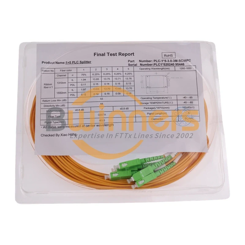
1×5 80/20 Unbalanced PLC Splitter, SC/APC, ABS Module, 3 m
Cassette PLC Splitter