BWN-PLC-MMST-1×8-NA-0.9mm
Bare Fiber PLC Splitter
1×8 Blockless Mini PLC Splitter, 0.9 mm, 2 m, No Connector
Proposed model: BWN-PLC-MMST-1×8-NA-0.9mm Factory/test part number shown on the supplied sample report: PLC-1*8-0.9-2M-NA Identity status: TBC — Product approval is required to confirm that these two identifiers refer to the same sellable SKU.

Proposed model: BWN-PLC-MMST-1×8-NA-0.9mm
Factory/test part number shown on the supplied sample report: PLC-1*8-0.9-2M-NA
Identity status: TBC — Product approval is required to confirm that these two identifiers refer to the same sellable SKU.
This proposed 1×8 PLC splitter uses a compact steel-tube package, 0.9 mm leads and no factory-installed connectors. It is intended for integration inside a compatible splice tray, closure or distribution enclosure where the host equipment provides fixation, bend control, fiber storage and environmental protection. Confirm the controlled model datasheet, drawing, optical limits and host-enclosure fit before ordering.
Compare blockless mini PLC splitter configurations or send the exact enclosure clearance, pigtail routing, optical-budget limits, quantity and document requirements for review.
Quick answer
The supplied photographs show a 1×8 PLC splitter marked PLC 1x8 0.9 2m NA, with one input, eight color-coded output pigtails, a compact steel-tube body and unterminated fiber ends. A photographed serial report records 1260–1650 nm, G657A fiber, 0.9 mm pigtails, 2 m length, a 60×7×4 mm package and connector NA for that sample. These fields must still be linked to the proposed commercial SKU through an approved product record.
Key configuration
| Field | Draft value | Evidence/status |
|---|---|---|
| Proposed BWNFiber model | BWN-PLC-MMST-1×8-NA-0.9mm | TBC — commercial/factory crosswalk required |
| Configuration | 1×8 PLC splitter | Observed on sample report |
| Split | Equal 1×8 | TBC — source Markdown states equal; controlled specification required |
| Package family | Blockless Mini / steel tube | Supported by physical package and BWNFiber taxonomy |
| Package size | 60×7×4 mm | Observed on sample report; drawing required for final fit approval |
| Fiber | G.657.A | Observed on sample report; A1/A2 subtype not confirmed |
| Pigtail construction | 0.9 mm | Observed on sample report/product marking |
| Pigtail length | 2 m | Observed on sample report/product marking |
| Connector | None / NA | Observed on sample report and photographs |
| Operating wavelength | 1260–1650 nm | Observed on sample report; model applicability requires approval |
| Operating/storage temperature | −40 to +85 °C | Sample-report field; model-wide limit TBC |
| Return loss / directivity | ≥50 dB / ≥55 dB | Sample-report field; model-wide limit TBC |
| Guaranteed insertion loss, PDL and uniformity | TBC — source required | Do not substitute serial readings or sibling-family values |
Technical-reference notice: values shown from the supplied Final Test Report describe the photographed serial unless an approved model datasheet or acceptance specification states otherwise. Final performance depends on the ordered configuration, test method, splices, terminations, host enclosure and link budget.
What the supplied sample report shows
The supplied photograph shows a report for serial PLC1*82024107099. A manual visual transcription indicates:
| Sample-only check | 1310 nm | 1550 nm | Publication boundary |
|---|---|---|---|
| Per-port insertion-loss range | approximately 9.77–9.96 dB | approximately 9.72–10.09 dB | HOLD until Quality checks transcription; not a guaranteed limit |
| Per-port PDL range | approximately 0.05–0.19 dB | approximately 0.06–0.20 dB | HOLD until Quality checks transcription; sample only |
| Reported return loss minimum | 50 dB | 50 dB | Sample-report field; model acceptance limit TBC |
| Reported directivity minimum | 55 dB | 55 dB | Sample-report field; model acceptance limit TBC |
The source Markdown contains a different per-port data set. Do not combine the two records. Publish a serial table only when the serial number, original report, transcription, test conditions and relationship to the shipped unit are verified.
Interfaces and termination boundary
This SKU is drafted as unterminated. It is not the same product as the existing 1×8 LC/APC or SC/APC steel-tube models. Connector family, polish, connector loss, end-face inspection and adapter compatibility do not apply until the project defines a downstream splice or termination plan.
- Do not describe
NAas a universal connector-compatible guarantee. - Define how the input and eight outputs will be fusion-spliced, protected and labeled.
- Confirm the splice-protector holders, storage route and cover clearance in the host tray.
- If factory connectors are required, use the exact connectorized sibling rather than changing this page's intent.
See the 1×8 LC/APC steel-tube PLC splitter for the connectorized LC/APC sibling.
Fiber and configuration boundary
The photographed report states G657A; it does not identify G.657.A1 or G.657.A2. Do not publish a subtype until Engineering supplies the controlled product record. The visible output colors help identify individual pigtails, but color alone is not an approved port map. A drawing or release record should define input/output numbering, color sequence and label requirements.
Compatibility and application conditions
Use this model only when all of the following are confirmed:
- The network design requires a 1×8 PLC split and the approved optical budget accepts the exact model limits.
- The host splice tray, closure or distribution enclosure has room for the steel tube, fiber exits, service slack and splice protection.
- The 0.9 mm leads are routed and protected within the limits in the approved drawing.
- Unterminated leads match the installer’s fusion-splice and labeling plan.
- The project accepts the exact fiber grade, wavelength range, test method and release documents.
Named-system claims such as GPON or XGS-PON remain TBC for this exact SKU until the optical budget and product specification are approved. For broader planning, use the PLC splitter selection page rather than treating this SKU page as a general network-design guide.
How to select and approve this exact configuration
- Freeze the identity. Confirm the BWNFiber SKU, factory part number and revision.
- Check the topology. Confirm 1×8, equal/unequal definition, cascade stage and per-path loss limits.
- Approve mechanical fit. Check 60×7×4 mm package, fiber exits, holder, bend control, service slack and cover clearance against the host-enclosure drawing.
- Approve fiber and termination. Confirm G.657 subtype, 0.9 mm construction, input/output lengths, splice method, color/port map and labels.
- Approve optical acceptance. Use the model datasheet and order acceptance limits; treat the photographed readings as sample evidence only.
- Freeze the release pack. Define which drawing, datasheet, serial report, inspection record and packaging label must accompany the order.
Differences from related products
| Product/page role | Key difference | Correct use |
|---|---|---|
| This proposed exact SKU | 1×8, steel tube, 0.9 mm, 2 m, no connector | Exact-model validation and RFQ |
| 1×8 LC/APC steel-tube sibling | Factory LC/APC termination | Connectorized LC/APC requirement |
| 1×8 SC/APC steel-tube sibling | Factory SC/APC termination | Connectorized SC/APC requirement |
| Bare Fiber PLC Splitter category | BWNFiber defines this family without the larger steel-tube package and generally around 250 µm routing | Minimum package volume where the host tray protects the assembly |
| Blockless Mini category | Compact steel-tube PLC family | Compare ratios, fiber/connector options and tray fit |
For the true bare-fiber family, see bare fiber PLC splitter options. Do not use that category label for this steel-tube sample.
Suitable and non-fit conditions
Potentially suitable after approval
- Protected splice trays with controlled 0.9 mm routing.
- Compatible fiber closures or distribution boxes that provide environmental sealing and mechanical protection.
- Custom integrated assemblies where the drawing freezes package position, pigtail routes, splices and labels.
Not a confirmed fit
- Direct outdoor exposure: the steel tube is not an outdoor enclosure and no IP rating is claimed.
- Plug-and-play adapter applications: this SKU has no connectors.
- Projects requiring a different split ratio, connector, fiber subtype or lead length without an approved order code.
- Any link whose loss budget has been checked only against the photographed sample rather than approved worst-case limits.
Testing and quality-control requirements
Before production release, request and approve:
- model datasheet and revision;
- dimensional drawing and fiber-exit/port map;
- insertion-loss, uniformity, PDL, return-loss and directivity acceptance limits;
- test wavelengths, method, equipment/calibration and pass/fail rules;
- serial-level optical report requirements;
- visual/label inspection criteria;
- packaging and traceability requirements;
- any project-specific compliance evidence with exact scope.
The supplied report shows useful sample evidence, but a RoHS mark on a photographed report is not a substitute for an applicable declaration or certificate.
Packaging and procurement information
| Field | Status |
|---|---|
| Quantity / MOQ | TBC — quotation required |
| Price / currency / validity | TBC — quotation required |
| Availability / lead time | TBC — quotation required |
| Packaging and label format | TBC — Product/Sales approval required |
| Warranty / return terms | TBC — approved commercial terms required |
| Custom options | TBC — do not promise until an approved option matrix exists |
Information required for an RFQ
Send:
- Required 1×8 topology and confirmation of equal or unequal split.
- Optical budget and maximum allowed loss for every path.
- Host enclosure/tray drawing and available package clearance.
- Required fiber grade/subtype and 0.9 mm lead construction.
- Input/output lead lengths, service slack and splice method.
- Port/color map and label convention.
- Required datasheet, drawing, test report and compliance documents.
- Quantity, sample requirement, target schedule and destination country.
Primary CTA: Submit the enclosure drawing, optical budget and exact configuration for an exact-model review.
Secondary CTA: Request the approved datasheet, dimensional drawing and model acceptance limits.
Datasheet, drawing and report area
- Controlled model datasheet: SOURCE REQUIRED
- Dimensional drawing / port map: SOURCE REQUIRED
- Model acceptance specification: SOURCE REQUIRED
- Supplied serial report: available as a first-party photograph; Quality approval and redaction/publication decision required
- Compliance documents: SOURCE REQUIRED
FAQ
1×8 Blockless Mini PLC Splitter, 0.9 mm, 2 m, No Connector FAQ
Is this a bare fiber PLC splitter?
Not under BWNFiber's current website taxonomy. The photographed product uses a steel-tube package and 0.9 mm leads, so it fits the Blockless Mini family. The Bare Fiber category is reserved for a less-protected form factor and should not own this exact page.
Does “NA” mean no connector?
The photographed report lists connector NA, and the supplied images show unterminated leads. Product must still approve the commercial SKU crosswalk before this is published as a model fact.
Are the photographed insertion-loss readings guaranteed?
No. They are serial-specific sample readings. Guaranteed limits must come from the approved model datasheet or order acceptance specification.
Can the product be installed outdoors?
Only inside a compatible outdoor-rated enclosure that provides sealing, fixation and fiber management. No IP rating is claimed for the splitter itself.
Is G.657.A1 or G.657.A2 used?
The supplied report states G657A only. The subtype is TBC and must be confirmed in the controlled datasheet.
What must be confirmed before a bulk order?
Freeze the SKU/part-number crosswalk, split definition, drawing, port map, fiber and pigtail construction, model acceptance limits, test/release documents, labels, packaging, quantity and schedule.
Related Products
Related Products
Explore additional fiber optic products related to this item and suitable for similar network deployment needs.

Cassette PLC Splitter
1×9 80/20 Uneven PLC Splitter, SC/APC, 3.0 mm × 3 m ABS Module

Cassette PLC Splitter
1×9 75/25 Unbalanced PLC Splitter with SC/APC and 3 m Leads
Cassette PLC Splitter
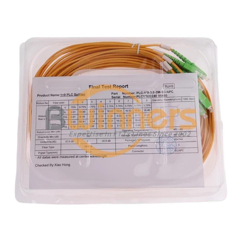
1×9 70/30 Unbalanced PLC Splitter, SC/APC, ABS Cassette, 3 m

Cassette PLC Splitter