BWNF-PLC-ABS-1×5-80-20-SCAPC-3M
Cassette PLC Splitter
1×5 80/20 Unbalanced PLC Splitter, SC/APC, ABS Module, 3 m
This 1×5 PLC splitter uses a nominal 80/5/5/5/5 output map: one output receives 80% of the input power and four outputs receive 5% each. The photographed configuration has SC/APC terminations, G657A 3.0 mm pigtails, 3 m length and a black module recorded as 100 × 80 × 10 mm on its test report. Use it only where the approved optical design calls for this unequal port map.

This 1×5 PLC splitter uses a nominal 80/5/5/5/5 output map: one output receives 80% of the input power and four outputs receive 5% each. The photographed configuration has SC/APC terminations, G657A 3.0 mm pigtails, 3 m length and a black module recorded as 100 × 80 × 10 mm on its test report. Use it only where the approved optical design calls for this unequal port map.
Primary CTA: Request an exact-model review and quotation. Send the required port map, OLT/ONT or system wavelengths, shortest and longest path budgets, host-module space, connector schedule, quantity, destination and required acceptance documents. BWNFiber should return a model-matched quotation and identify any missing specification or evidence before order release. TBC — sales/engineering workflow approval required.
Short answer for buyers
This is not an equal 1×5 splitter. The supplied label and report show one nominal 80% output and four nominal 5% outputs. Confirm the physical output labels before installation, and use maximum approved device loss—not the nominal power percentage or this one-unit example—when closing each route budget. The ABS module still requires a suitable host enclosure and approved routing space.
Technical-reference disclaimer: The measured figures below apply only to the photographed report/unit and are not a guarantee for another serial number or order. Final design and acceptance must use an approved model datasheet, order specification and project test method.
Key configuration facts
- 1 input and 5 outputs
- Nominal output map: 80/5/5/5/5
- SC/APC terminations on the photographed unit
- G657A fiber recorded on the report; A1/A2 subtype is
TBC - 3.0 mm pigtails, 3 m length
- Reported operating wavelength: 1260–1650 nm
- Reported module size: 100 × 80 × 10 mm
- Serial-level IL and PDL results recorded at 1310 nm and 1550 nm
Technical specifications
| Field | Evidence-bounded value | Release note |
|---|---|---|
| Product type | 1×5 unequal/unbalanced PLC splitter | Supported by label/report |
| Public BWNFiber SKU | TBC — source uses BWNF-PLC-ABS-1x5-80-20-SCAPC-3M | Must be reconciled with physical identifiers |
| Physical part-number form | Label shows PLC-B-1X5-3.0-3M-SC/APC | Report formatting differs; owner must approve alias map |
| Nominal port map | 80/5/5/5/5 | Supported by label/report |
| Package | Black ABS module | Material name needs product-owner confirmation; black module is visible |
| Package dimensions | 100 × 80 × 10 mm | Report value; request a dimensioned drawing for fit approval |
| Connector | SC/APC | Supported by label/report/photos |
| Fiber | G657A | A1/A2 subtype not established |
| Pigtail diameter | 3.0 mm | Supported by label/report |
| Pigtail length | 3 m | Supported by label/report |
| Operating wavelength | 1260–1650 nm | Report value |
| Operating temperature | −40 °C to +85 °C | Report value; method/reliability evidence not supplied |
| Storage temperature | −40 °C to +85 °C | Report value; method/reliability evidence not supplied |
| Return loss | 55 dB | Report value; exact acceptance operator/method to confirm |
| Directivity | 55 dB | Report value; test method to confirm |
| Tap-port uniformity | ≤0.8 dB | Report value for the four 5% outputs |
| Compliance | TBC — controlled evidence required | Telcordia or RoHS compliance requires model-specific documentation |
Port map: do not interpret 80/20 as two outputs
| Physical label / logical role | Nominal share | Installation control |
|---|---|---|
| IN | Input | Confirm against the approved port schedule |
| 80% output | 80% | Assign its network role in the approved ODN or optical design |
| 5% output 1 | 5% | Record destination and route budget |
| 5% output 2 | 5% | Record destination and route budget |
| 5% output 3 | 5% | Record destination and route budget |
| 5% output 4 | 5% | Record destination and route budget |
The two-number description 80/20 is shorthand for one 80% path plus four outputs sharing the other 20%. Put the complete 80/5/5/5/5 map on the quotation, drawing, label schedule and acceptance record.
Example measured results for the photographed unit
The values below are transcribed from the supplied Final Test Report for the photographed unit. They are evidence for that report/serial, not guaranteed maxima for every unit or order. A released datasheet and order-specific acceptance limits must control design and procurement.
| Output | Nominal share | IL at 1310 nm | PDL at 1310 nm | IL at 1550 nm | PDL at 1550 nm |
|---|---|---|---|---|---|
| P1 | 80% | 1.63 dB | 0.09 dB | 1.71 dB | 0.20 dB |
| P2 | 5% | 14.83 dB | 0.17 dB | 14.93 dB | 0.16 dB |
| P3 | 5% | 14.92 dB | 0.12 dB | 14.75 dB | 0.11 dB |
| P4 | 5% | 14.76 dB | 0.15 dB | 14.82 dB | 0.11 dB |
| P5 | 5% | 14.84 dB | 0.19 dB | 14.83 dB | 0.18 dB |
Do not use nominal split percentages as insertion-loss values. For a design, use approved maximum IL at every required wavelength and include connectors, splices, fiber, other passive devices and design reserve. Each shortest and longest path must pass separately.
For the system-level method, build the end-to-end fiber loss budget and validate the splitter against the approved ODN design.
Interfaces and host conditions
The photographed assembly uses SC/APC connectors on 3.0 mm pigtails. Match APC interfaces only to compatible APC adapters and clean/inspect every end face before connection. Do not mix APC and UPC interfaces.
The ABS module is not a stand-alone outdoor enclosure claim. Before approving the host box, verify:
- available mounting area against a dimensioned drawing;
- pigtail exit direction and strain control;
- routing clearance and minimum bend limits for the complete pigtail construction;
- adapter or pass-through capacity for the input and five outputs;
- environmental, sealing, fire, UV and mechanical duties assigned to the host enclosure.
Application and compatibility conditions
This unequal port map can be evaluated for an approved distributed or cascaded optical design that needs one higher-power path and four lower-power paths. The network owner or authorized designer must assign the ports and verify every path.
Do not infer GPON, XGS-PON, CATV, LAN, equipment-brand or reach compatibility from the splitter label alone. Confirm wavelengths, transmitter/receiver limits, minimum and maximum path loss, connector interfaces, other passive devices and the installed acceptance method.
Non-fit conditions
Do not use this configuration when:
- the design requires five equal outputs;
- the approved port map or output labels differ;
- the 80% or any 5% path fails its allowed loss window;
- the host lacks verified module space, pigtail routing or connector capacity;
- the project requires an IP, flame, UV, waterproof or mechanical rating that has not been established for the complete installed assembly;
- the procurement specification requires a certification or compliance record that is not available for the exact order.
How to select and release the correct configuration
- Freeze the full nominal map as
80/5/5/5/5; do not issue a PO using only1×5 PLC. - Assign each physical output to a named route or function in the approved design.
- Calculate the shortest and longest path at every required wavelength using approved maximum values.
- Confirm the host dimensions, mounting, exits, routing, connector polish and dust protection.
- Reconcile the public SKU, label part number, drawing number and test-report identifier.
- Agree on the datasheet revision, sample plan, acceptance limits, test wavelengths and report format.
- Release the quotation/PO only after open items have owners and due dates.
Difference from related splitter options
| Option | Primary difference | Do not substitute when… |
|---|---|---|
| Equal 1×4 or 1×8 PLC splitter | All outputs are intended to be nominally equal | The approved design requires one 80% path and four 5% paths |
| 1×5 85/15 unequal splitter | Different high-power/remainder allocation | The route budgets require the 80/5×4 map |
| Blockless/steel-tube 1×5 splitter | Different package and host-integration conditions | The approved drawing calls for this ABS module and its pigtail exits |
| FBT unequal coupler | Different component architecture and model limits | The design and acceptance specification names a PLC 1×5 configuration |
This table is a configuration screen, not a universal performance comparison. Compare approved model records rather than technology labels.
To browse broader options without mixing their specifications into this record, compare cassette PLC splitter configurations, review the PLC splitter product range, or open the fiber optic splitter product directory.
Testing and acceptance
The supplied report provides a useful example of per-output IL and PDL at 1310 nm and 1550 nm. Before an order is released, define:
- whether values are maximum limits or measured results;
- test wavelengths and launch/reference method;
- whether connectors are included in the test plane;
- instrument calibration and report traceability requirements;
- return-loss/directivity method and acceptance operator;
- sampling level or 100% test requirement;
- retest and nonconformance disposition;
- relationship among SKU, label, serial number, report and packing list.
TBC — BWNFiber QA must confirm the standard test/release process and which documents can be supplied.
Packaging and procurement information
MOQ, unit price, stock, lead time, packaging, warranty, Incoterms and document availability are TBC — commercial source required. Do not reuse values from third-party marketplaces or the Sijee page without a current BWNFiber quotation and owner approval.
Required RFQ information
Send:
- project name and destination country;
- required full output map:
80/5/5/5/5; - intended port assignment and network diagram;
- system wavelengths and equipment models/classes;
- shortest and longest path-loss worksheets;
- host-enclosure drawing and available module/routing space;
- SC/APC input/output schedule and label requirements;
- pigtail diameter and length;
- quantity and requested delivery date;
- required datasheet, drawing, test report, declaration/certificate and inspection scope;
- sample qualification and batch acceptance requirements.
Downloads — HOLD until approved
- Model datasheet:
TBC — source required - Dimensioned drawing:
TBC — source required - Blank/example test-report format:
TBC — QA approval required - Exact-SKU compliance declaration/certificate:
TBC — source required
Do not offer a download until the controlled file, revision, model applicability and public URL have been verified.
FAQ
1×5 80/20 Unbalanced PLC Splitter, SC/APC, ABS Module, 3 m FAQ
What does 80/20 mean on this 1×5 splitter?
For the supplied configuration, it means one nominal 80% output and four nominal 5% outputs: 80/5/5/5/5. It does not mean one 80% output and one 20% output.
Is this an equal 1×5 splitter?
No. The label and report show unequal outputs. An equal splitter or another unequal ratio is not a like-for-like substitute.
Are the values in the optical table guaranteed limits?
No. They are transcribed example measurements from the supplied report for one photographed unit. Use the approved datasheet and order-specific acceptance limits for design and purchasing.
Does the splitter itself prove GPON or XGS-PON compatibility?
No. The operating band is one input. The system design still has to verify equipment limits, every optical path, coexistence devices, interfaces and the acceptance method.
Can the ABS module be installed outdoors by itself?
No outdoor or IP rating has been established. The approved host enclosure must provide the required environmental and mechanical protection.
What should be checked before placing an order?
Confirm the full port map, port assignments, path budgets, module fit, pigtail construction, connectors, model/label mapping, document revision, test scope, quantity and commercial terms.
Is this product Telcordia or RoHS compliant?
TBC — exact-SKU controlled evidence is required. A family-page statement or a logo on a report is not enough to make the claim here.
Can other connectors, lengths or fiber constructions be ordered?
TBC — current option matrix and quotation required. Do not assume a family option applies to this exact SKU.
Related Products
Related Products
Explore additional fiber optic products related to this item and suitable for similar network deployment needs.

Cassette PLC Splitter
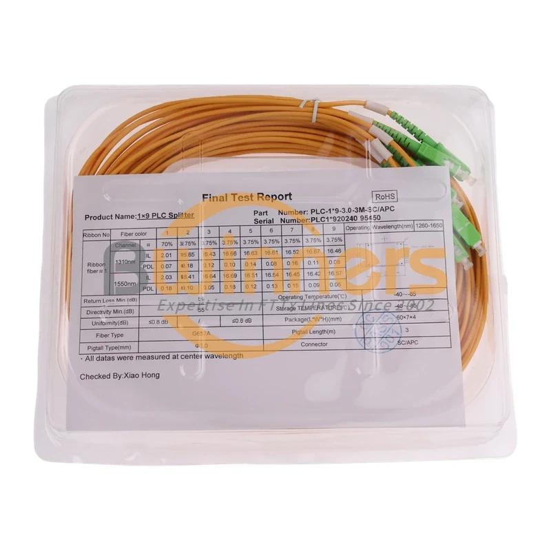
1×9 80/20 Uneven PLC Splitter, SC/APC, 3.0 mm × 3 m ABS Module

Cassette PLC Splitter
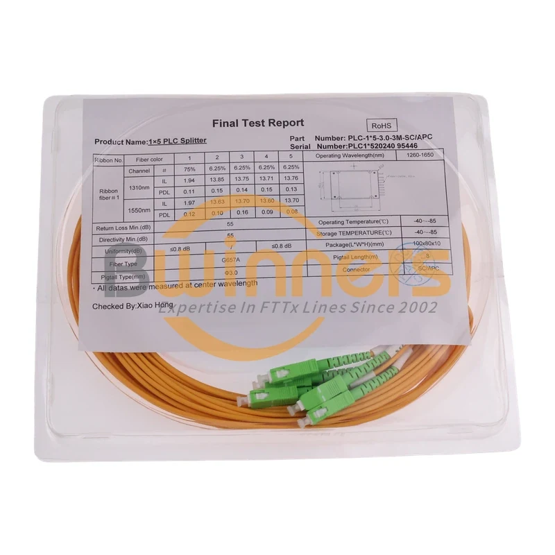
1×9 75/25 Unbalanced PLC Splitter with SC/APC and 3 m Leads
Cassette PLC Splitter
1×9 70/30 Unbalanced PLC Splitter, SC/APC, ABS Cassette, 3 m
Cassette PLC Splitter