BWNF-PLC-ABS-1×5-75-25-SCAPC-3M
Cassette PLC Splitter
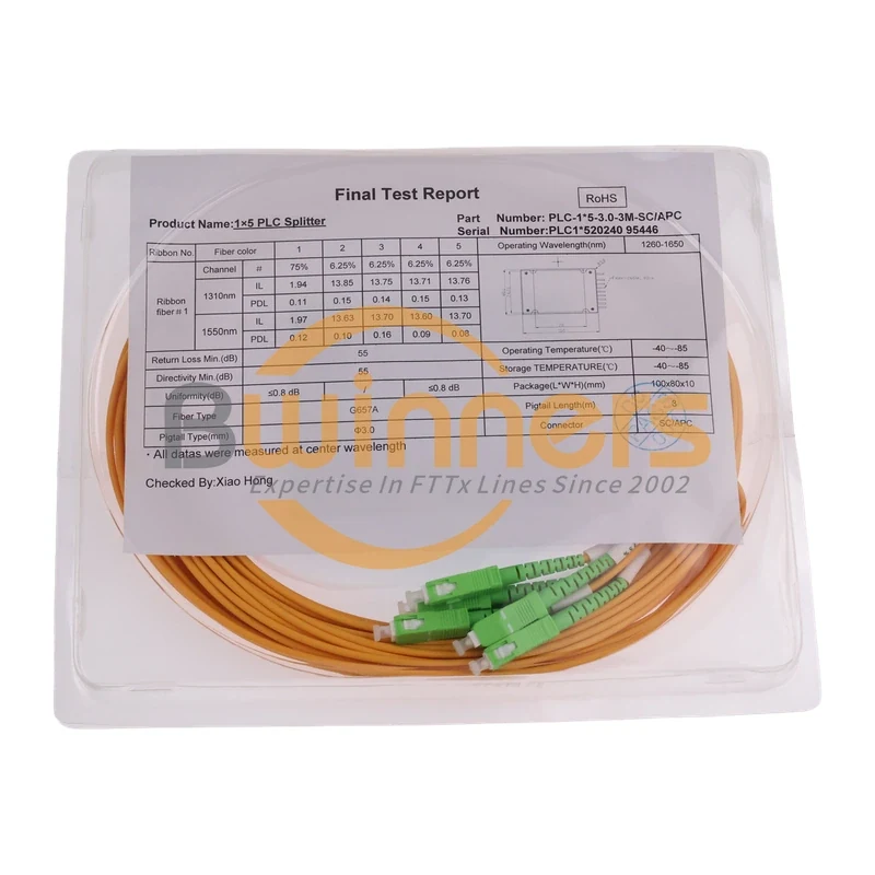
1×5 75/25 PLC Splitter, SC/APC, 3.0 mm, 3 m
This 1×5 unbalanced PLC splitter provides one nominal 75% cascade output and four nominal 6.25% tap outputs, with SC/APC connectors and 3.0 mm, 3 m pigtails.
Model proposed for publication: BWNF-PLC-ABS-1×5-75-25-SCAPC-3M
Product status: TBC — Product Owner approval required
This 1×5 unequal PLC splitter configuration sends a nominal 75% share to one express path and divides the remaining 25% equally across four service taps, or 6.25% per tap. The supplied build records SC/APC connectors, G657A fiber, 3.0 mm pigtails, a 3 m pigtail length, and a 1260–1650 nm operating window.
Use this page to validate the exact port map and the supplied sample results before requesting this configuration. For other output counts, ratios, packages, or interfaces, start with the uneven PLC splitter family rather than treating this model as a universal substitute. If PLC is not yet the approved splitter technology, use the fiber optic splitter directory to route the requirement before selecting an exact model.
Quick Answer
On this 1×5 build, “75/25” does not mean two output ports. It means one output is assigned 75%, while four additional outputs share the remaining 25% at 6.25% each. Optical power and insertion loss are different quantities; use the approved per-port loss limits and the full link budget for design acceptance. In quote records, the configuration may be written as 1x5 75/6.25x4 PLC splitter; confirm the 1x5 SC/APC 75/25 PLC splitter interface and the 1x5 PLC splitter 3.0 mm 3 m construction as separate order fields. The table below is the controlling 75/25 PLC splitter port map for this offline draft.
Exact configuration at a glance
| Order field | Recorded configuration | Evidence status |
|---|---|---|
| Input / outputs | 1 × 5 | Supplied report and label |
| Nominal port map | 75% / 6.25% / 6.25% / 6.25% / 6.25% | Supplied report and tail labels |
| Connector | SC/APC | Supplied report and photos |
| Fiber wording | G657A | Supplied report; A1/A2 subclass not stated |
| Pigtail diameter | 3.0 mm | Supplied report and label |
| Pigtail length | 3 m | Supplied report and label |
| Operating wavelength | 1260–1650 nm | Supplied report |
| Housing | Black module; ABS material confirmation pending | Photo observed; material record required |
| Reported sample size | 100 × 80 × 10 mm | Supplied report; production tolerance TBC |
| Proposed SKU | BWNF-PLC-ABS-1×5-75-25-SCAPC-3M | Product Owner mapping TBC |
Port map: identify the express path and four taps
| Port | Nominal share | Intended identification in supplied photos | Design action |
|---|---|---|---|
| Input | 100% entering device | IN | Confirm input direction before installation |
| P1 | 75% | 75% | Treat as the high-power/express path only after label verification |
| P2 | 6.25% | 6.25% | Include its approved IL in the subscriber-path budget |
| P3 | 6.25% | 6.25% | Include its approved IL in the subscriber-path budget |
| P4 | 6.25% | 6.25% | Include its approved IL in the subscriber-path budget |
| P5 | 6.25% | 6.25% | Include its approved IL in the subscriber-path budget |
Before splicing or connecting the assembly, match the physical tail labels to the approved drawing or report. Do not infer the 75% path from fiber position, coil direction, or connector order alone.
Supplied sample test results
The following values are transcribed from the supplied Final Test Report dated 2024-09-28. They describe the reported sample/build and are not a promise that every unit will have identical readings. Engineering must approve the model's guaranteed maximum/minimum limits and the public use of any serial-level report.
| Port | Nominal share | IL at 1310 nm (dB) | PDL at 1310 nm (dB) | IL at 1550 nm (dB) | PDL at 1550 nm (dB) |
|---|---|---|---|---|---|
| P1 | 75% | 1.94 | 0.11 | 1.97 | 0.12 |
| P2 | 6.25% | 13.85 | 0.15 | 13.63 | 0.10 |
| P3 | 6.25% | 13.75 | 0.14 | 13.70 | 0.16 |
| P4 | 6.25% | 13.71 | 0.15 | 13.60 | 0.09 |
| P5 | 6.25% | 13.76 | 0.13 | 13.70 | 0.08 |
The supplied report also records return loss and directivity minimum values of 55 dB, tap-port uniformity of no more than 0.8 dB, and operating/storage temperature ranges of −40 °C to +85 °C. Publication as guaranteed model limits is TBC — engineering approval and a controlled datasheet are required. The report states that values were measured at center wavelength; instrument, method, uncertainty, and acceptance-revision details were not supplied.
Application and non-fit conditions
This ratio can be considered when a passive optical design needs one higher-power continuation path and four lower-power local taps. Acceptance depends on the complete design: transmitter/receiver classes, every splitter stage, connector and splice loss, fiber attenuation, operating wavelength, route length, repair margin, and required engineering reserve.
Do not use this product record as proof that the assembly is suitable for a named GPON, XGS-PON, CATV, LAN, OLT, ONT, or third-party platform. Compatibility and application approval are TBC — project data and engineering review required.
This exact page is not the right source when you need:
- an equal 1×4, 1×8, or other balanced split;
- a different high-power ratio;
- a blockless, bare-fiber, LGX, or rack-mounted package;
- a connector or polish other than the recorded SC/APC interface;
- a different pigtail diameter or length;
- a compliance certificate or a guaranteed model drawing not included in the approved document pack.
Browse the PLC splitter range for family-level selection, then return to the exact model record for order verification.
How to validate this model before ordering
- Confirm that
BWNF-PLC-ABS-1x5-75-25-SCAPC-3Mis the approved commercial model for the supplied configuration. - Attach the network loss budget and state which path must remain the 75% continuation path.
- Confirm 1×5 and the full ratio string: 75/6.25×4.
- Confirm SC/APC on all six ends, G657A fiber wording, 3.0 mm pigtails, and 3 m length.
- Confirm the host enclosure, available routing space, bend control, and required module dimensions/tolerances.
- Define guaranteed IL, PDL, return-loss, directivity, and uniformity limits for the purchase order.
- Specify required documents: controlled datasheet, drawing, per-unit or batch test report, packing list, and any verified compliance record.
- Approve the tail-label convention before production and check it at incoming inspection.
What to send for an RFQ
Use the exact model in the subject line and provide:
- quantity and required delivery location/date;
- network type and operating wavelengths;
- approved loss budget for the express and tap paths;
- 1×5 and 75/6.25×4 port map;
- SC/APC, fiber grade, pigtail diameter, and length;
- host box/closure and available module/routing space;
- required guaranteed optical limits;
- tail-label and packaging/label requirements;
- document and inspection requirements;
- sample, pilot, or batch-approval requirement.
Primary CTA: Request an exact-model review and quotation. Include the proposed SKU, 75/6.25×4 ratio, quantity, host enclosure, and path-loss budget.
Secondary CTA: Review the uneven PLC family page if the ratio, output count, package, or interface is not fixed.
FAQ
1×5 75/25 PLC Splitter, SC/APC, 3.0 mm, 3 m FAQ
What does 75/25 mean on this 1×5 PLC splitter?
For the supplied build, one output is nominally 75%. The other four outputs divide the remaining 25% equally, so each is nominally 6.25%. Write the full port map as 75/6.25×4 in the RFQ to avoid treating this as a two-output or equal-split device.
Is 75% optical power the same as 1.25 dB insertion loss?
No. The nominal power ratio describes allocation; the measured insertion loss includes device and interface effects. The supplied sample report records 1.94 dB at 1310 nm and 1.97 dB at 1550 nm on its 75% path. Use approved model limits, not a ratio-only calculation, for acceptance.
Do the table values apply to every unit?
No. They are transcribed from one supplied report/build. The quotation, controlled datasheet, and agreed inspection plan must define the guaranteed limits and whether a per-unit or batch report will be supplied.
How do I identify the 75% output?
The supplied photos show one tail labeled 75%, four tails labeled 6.25%, and an input labeled IN. Confirm the shipped labeling against the approved drawing/report; do not rely on physical tail order alone.
Can I replace this with an equal 1×4 or 1×8 splitter?
Not without redesigning and re-approving the optical budget. Equal splitters do not provide the same 75% continuation path and four 6.25% taps.
Is this product certified to RoHS or Telcordia requirements?
TBC — source required. A RoHS mark is visible on the supplied report image, but no model-level declaration/certificate or Telcordia qualification evidence was supplied for this review. Do not place those claims on the public page until Compliance verifies the exact documents and scope.
Related Products
Related Products
Explore additional fiber optic products related to this item and suitable for similar network deployment needs.

Cassette PLC Splitter
1×9 80/20 Uneven PLC Splitter, SC/APC, 3.0 mm × 3 m ABS Module

Cassette PLC Splitter
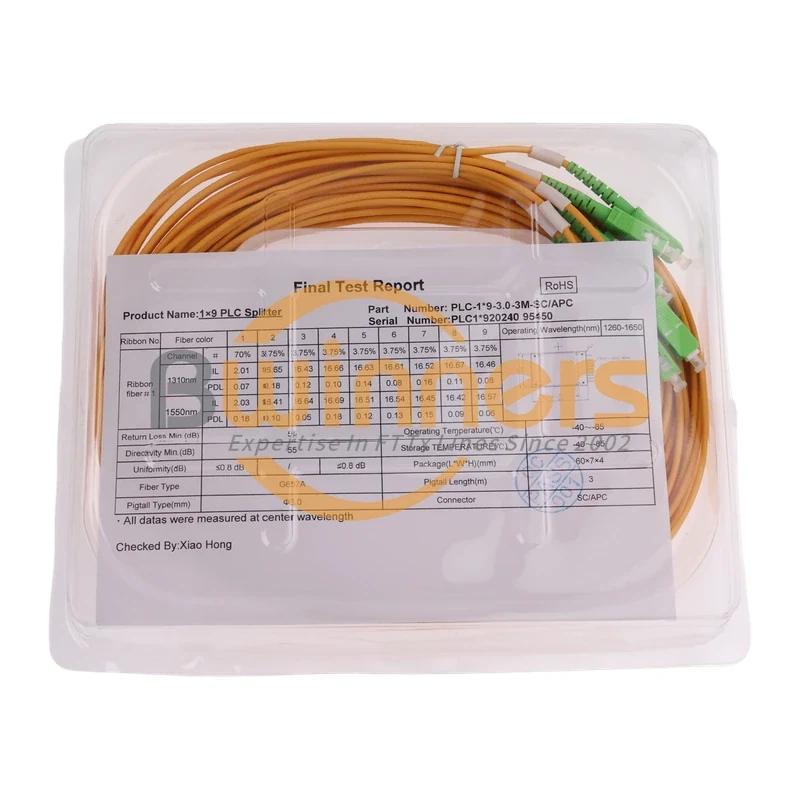
1×9 75/25 Unbalanced PLC Splitter with SC/APC and 3 m Leads
Cassette PLC Splitter
1×9 70/30 Unbalanced PLC Splitter, SC/APC, ABS Cassette, 3 m

Cassette PLC Splitter