BWNF-PLC-ABS-1×5-70-30-SCAPC-3M
Cassette PLC Splitter
1×5 70/30 Unbalanced PLC Splitter, SC/APC ABS Module
This 1×5 unbalanced PLC splitter provides one nominal 70% cascade output and four nominal 7.5% tap outputs, with SC/APC connectors and 3 m leads in an ABS module.

Model: BWNF-PLC-ABS-1×5-70-30-SCAPC-3M
Configuration: 1 input × 5 outputs; 70% high-power path + four nominal 7.5% tap paths
Termination: SC/APC on G.657A, 3.0 mm, 3 m pigtails
Package: ABS module; sample-build report lists 100 × 80 × 10 mm
This 1×5 unbalanced PLC splitter divides one optical input into one nominal 70% path and four nominal 7.5% paths. The expanded ratio is 70/7.5%×4. Use that complete port map when reviewing the network design, label schedule, optical budget and purchase order; 70/30 alone does not show how the remaining 30% is divided.
Primary action: Request a model review and quotation with your topology, allowable path loss, quantity and required document pack.
What Does 70/30 Mean on This 1×5 Splitter?
The label uses 70/7.5/7.5/7.5/7.5. One output is the nominal 70% path. The other four outputs share the nominal remaining 30%, giving 7.5% per tap. This is not an even 1×5 splitter, and an equal-split 1×N loss table must not be used as its acceptance table.
| Port role | Nominal power allocation | Buyer/installer check |
|---|---|---|
| Input | 100% input | Confirm the input label and connector |
| High-power output | 70% | Confirm which physical lead carries the 70% label |
| Tap 1 | 7.5% | Match the lead label to the approved port schedule |
| Tap 2 | 7.5% | Match the lead label to the approved port schedule |
| Tap 3 | 7.5% | Match the lead label to the approved port schedule |
| Tap 4 | 7.5% | Match the lead label to the approved port schedule |
The 70% path can be considered for a downstream node and the four 7.5% paths for local branches only after the network designer confirms the complete topology and end-to-end power budget. The ratio does not by itself prove compatibility with a particular OLT, ONT, wavelength plan or cascade count.
Confirmed Configuration for the Photographed Build
| Attribute | Evidence-bounded value |
|---|---|
| Proposed public model | BWNF-PLC-ABS-1×5-70-30-SCAPC-3M — mapping approval pending |
| Factory part number shown | PLC-B-1X5-3.0-3M-SC/APC |
| Input/output | 1 × 5 |
| Nominal ratio | 70/7.5%×4 |
| Connector | SC/APC |
| Fiber shown on report | G657A |
| Pigtail construction | 3.0 mm, 3 m |
| Operating wavelength shown | 1260–1650 nm |
| ABS module size shown | 100 × 80 × 10 mm |
| Operating temperature shown | −40°C to +85°C |
| Storage temperature shown | −40°C to +85°C |
The photographs and report support the pictured build. A controlled drawing and approved production datasheet are still required before dimensions, tolerances or limits are treated as guaranteed order specifications.
Sample-Build Optical Test Record
The following readings are transcribed from the photographed final test report for the pictured serial/build. They are sample-build measurements, not production guarantees. Before placing an order, request the approved maximum/minimum acceptance limits, test conditions and document-delivery requirement for the ordered model.
| Port | Nominal role | IL at 1310 nm | PDL at 1310 nm | IL at 1550 nm | PDL at 1550 nm |
|---|---|---|---|---|---|
| P1 | 70% high-power path | 2.17 dB | 0.10 dB | 2.17 dB | 0.09 dB |
| P2 | 7.5% tap | 13.16 dB | 0.05 dB | 13.11 dB | 0.07 dB |
| P3 | 7.5% tap | 13.11 dB | 0.15 dB | 13.18 dB | 0.14 dB |
| P4 | 7.5% tap | 13.10 dB | 0.12 dB | 13.09 dB | 0.12 dB |
| P5 | 7.5% tap | 13.16 dB | 0.12 dB | 13.16 dB | 0.08 dB |
The same report lists a minimum return loss of 55 dB, minimum directivity of 55 dB and tap-port uniformity of no more than 0.8 dB. QA confirmation is required before those lines are published as acceptance limits.
For planning, evaluate every path. Do not budget only the 70% output and assume the four taps are equivalent to an even splitter. The network designer should use the approved worst-case limits for the ordered unit, then add connector, splice, fiber, engineering-margin and any additional cascade losses. See the fiber splitter loss and link-budget guide for the general calculation owner; this page remains the model record.
Package, Fiber and Interface
The photographed unit has a black ABS module and six SC/APC-terminated, orange 3.0 mm pigtails. The report identifies G657A fiber and 3 m pigtail length. The exact G.657 category suffix, cable construction, bend limit, connector grade, dust-cap requirement and material/flammability properties are not established by the supplied evidence.
Choose this physical build only when the approved host box or cabinet provides enough space for the module, cable exits, routing slack and connector access. A report-listed 100 × 80 × 10 mm package size is useful for preliminary fit review; use an approved drawing for final mechanical release.
For other package formats or unequal configurations, review the uneven PLC splitter family. For the broader technology and package shortlist, use the PLC splitter category.
When This Configuration May Fit — and When It Does Not
This model may fit a design that requires one higher-power continuation path plus four lower-power local branches in a connectorized ABS module. Fit is conditional on the approved port assignment, link budget, operating wavelengths, host enclosure, environmental conditions and maintenance method.
Do not release this model when:
- the design requires equal power at all outputs;
- the available host space or fiber routing has not been checked against an approved drawing;
- the order record says only
1×5 PLC splitterand omits the 70/7.5%×4 mapping; - an APC/UPC interface mismatch exists;
- the end-to-end budget uses sample readings instead of approved worst-case limits;
- the required compliance, qualification or shipment documents have not been agreed in writing.
For an equal-output product or another package, start from the fiber optic splitter catalog rather than substituting by port count alone.
How to Specify the Correct Model
- State
1 input × 5 outputsand the complete70/7.5%×4port map. - Identify the physical high-power output and all four tap labels.
- Confirm the approved maximum IL/PDL, return loss, directivity and uniformity at the required test wavelengths.
- Specify SC/APC, fiber grade, 3.0 mm construction, 3 m length and ABS package—or submit the exact approved alternatives.
- Provide the host enclosure and routing constraints; attach a drawing when mechanical fit is critical.
- State the required datasheet, drawing, test report, declaration/certificate, label and packing-list deliverables.
- Include quantity, destination and schedule for a commercial quotation.
RFQ Checklist
Send BWNFiber:
- model or reference item;
- 1×5 and
70/7.5%×4ratio convention; - topology or diagram and allowable loss for every path;
- connector/polish and port-label schedule;
- fiber grade, pigtail diameter and length;
- module/drawing constraints and host enclosure;
- optical acceptance limits and test wavelengths;
- required datasheet, drawing, test report and compliance documents;
- quantity, destination and requested schedule.
What BWNFiber should return — pending internal approval: a configuration review, model-matched quotation and a list of available controlled documents. Do not promise a datasheet, drawing, sample or test report until Sales/QA confirms availability.
FAQ
1×5 70/30 Unbalanced PLC Splitter, SC/APC ABS Module FAQ
Is 70/30 an even split across five outputs?
No. On this photographed 1×5 build, the full nominal map is 70/7.5%×4: one high-power output and four equal lower-power taps.
Are the optical values on this page guaranteed production limits?
No. The table reproduces readings from the pictured sample-build report. Request the approved acceptance limits and test conditions for the ordered model.
Can an even 1×4, 1×5 or 1×8 replace this unit?
Not by port count alone. An equal splitter does not reproduce the 70% continuation path and four 7.5% taps. Any substitute needs a new topology and power-budget approval.
Does SC/APC fit an SC/UPC adapter or mating connector?
APC and UPC polish should not be treated as interchangeable. Confirm the complete mating interface and adapter schedule before release.
Does the ABS module automatically mean outdoor rated?
No. ABS describes the module package in the supplied record. No IP, UV, water-ingress or outdoor-enclosure rating was provided.
Which value should be used in the optical budget?
Use approved worst-case limits for each ordered path, not only a nominal split percentage or one sample result. Include every connector, splice, fiber section, cascade stage and design margin.
Can other connectors or pigtail lengths be ordered?
TBC — source required. An approved option matrix was not supplied for this SKU.
Is this model RoHS or Telcordia compliant?
TBC — model-level evidence required. A RoHS logo is visible on the photographed report, but no declaration/certificate was supplied; no SKU-level Telcordia qualification record was supplied.
Related Products
Related Products
Explore additional fiber optic products related to this item and suitable for similar network deployment needs.

Cassette PLC Splitter
1×9 80/20 Uneven PLC Splitter, SC/APC, 3.0 mm × 3 m ABS Module

Cassette PLC Splitter
1×9 75/25 Unbalanced PLC Splitter with SC/APC and 3 m Leads
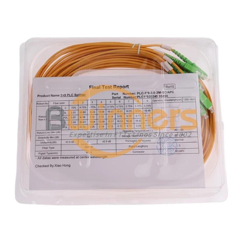
Cassette PLC Splitter
1×9 70/30 Unbalanced PLC Splitter, SC/APC, ABS Cassette, 3 m

Cassette PLC Splitter