BWNF-PLC-ABS-1×3-90-10-SCAPC-3M
Cassette PLC Splitter
1×3 90/5/5 SC/APC PLC Splitter in ABS Module, 3.0 mm × 3 m
This 1×3 unbalanced PLC splitter has one input, one output labeled 90%, and two outputs labeled 5% each. The photographed build uses SC/APC connectors, G657A fiber, 3.0 mm pigtails, 3 m length, and a 100 × 80 × 10 mm ABS module. Use the physical 90/5/5 map—not the two-number catalog shorthand alone—when preparing the BOM, port schedule, optical budget, and test plan.

Model: BWNF-PLC-ABS-1×3-90-10-SCAPC-3M
This 1×3 unbalanced PLC splitter has one input, one output labeled 90%, and two outputs labeled 5% each. The photographed build uses SC/APC connectors, G657A fiber, 3.0 mm pigtails, 3 m length, and a 100 × 80 × 10 mm ABS module. Use the physical 90/5/5 map—not the two-number catalog shorthand alone—when preparing the BOM, port schedule, optical budget, and test plan.
Evidence note: The optical values below come from the supplied final-test report for one photographed sample. They are sample-unit measurements, not guaranteed production limits. Request the approved model specification and order acceptance limits before release.
Technical reference notice: This page supports product identification and RFQ preparation only. It is not a network design approval, contractual specification, certification record, or performance guarantee. Use the project's approved drawings, product limits, link budget, test method, and responsible engineer's review for release.
Primary CTA — Request the model specification and quotation: Send the route or application, required port map, maximum accepted loss by path, connector, fiber, pigtail length, host enclosure, quantity, and required document pack. BWNFiber can return a configuration review and quotation after the specification is confirmed.
What does 90/10 mean on this 1×3 splitter?
For this exact build, 90/10 is catalog shorthand for a three-output distribution:
| Physical lead | Function in a proposed tap chain | Nominal share |
|---|---|---|
IN | Common input | 100% input reference |
90% | High-power continuing output | 90% |
5% | Local output 1 | 5% |
5% | Local output 2 | 5% |
The product photographs and sample test report show the output labels as 90%, 5%, and 5%. That mapping must remain consistent across the approved drawing, product label, BOM, enclosure port schedule, field labels, and test record.
Do not interpret this product as an even 1×3 splitter. Do not treat it as a two-output 90/10 FBT coupler. If the design needs one 90% main path and one 10% tap, use a two-output product specified for that topology. If the design needs three equal outputs, use an even 1×3 model with its own loss limits.
Exact configuration recorded for the supplied sample
| Attribute | Recorded configuration | Evidence boundary |
|---|---|---|
| BWNFiber model | BWNF-PLC-ABS-1×3-90-10-SCAPC-3M | Proposed SKU; product owner to approve |
| Product type | 1×3 PLC splitter | Visible product label and sample report |
| Output distribution | 90% / 5% / 5% | Visible lead labels and report channel row |
| Connector | SC/APC on input and outputs | Sample report and photographs |
| Fiber | G657A | Report does not identify A1 or A2 |
| Pigtail construction | Φ3.0 mm, 3 m | Product label and sample report |
| Package | Black ABS module | Photographs; resin grade not supplied |
| Recorded package size | 100 × 80 × 10 mm | Sample report; confirm drawing and tolerances |
| Recorded operating wavelength | 1260–1650 nm | Sample report |
| Recorded operating temperature | −40 to +85 °C | Sample report; approve as model limit before release |
| Recorded storage temperature | −40 to +85 °C | Sample report; approve as model limit before release |
| Recorded return loss | ≥55 dB | Sample report; approve model/lot scope |
| Recorded directivity | ≥55 dB | Sample report; approve model/lot scope |
Sample-unit insertion loss and PDL
The supplied report records the following values at its stated center wavelengths. The physical port identity is part of the result; a single generic “1×3 insertion loss” value would hide the difference between the continuing and local paths.
| Port | Nominal output | IL at 1310 nm | PDL at 1310 nm | IL at 1550 nm | PDL at 1550 nm |
|---|---|---|---|---|---|
| P1 | 90% | 0.74 dB | 0.18 dB | 0.76 dB | 0.08 dB |
| P2 | 5% | 13.74 dB | 0.11 dB | 13.81 dB | 0.09 dB |
| P3 | 5% | 13.84 dB | 0.09 dB | 13.77 dB | 0.19 dB |
These values describe the supplied sample as recorded. For network design and incoming inspection, use the approved maximum and minimum limits for the ordered model, wavelength, direction, connectors, environmental condition, and test reference planes. Do not copy the sample readings into a contractual budget as guaranteed maxima.
Where this configuration may fit
This configuration may be evaluated for a distributed optical tap node where one output continues downstream and two lower-power outputs serve local branches. The nominal ratio is only the starting point. Approval still requires:
- the exact input, continuing output, and local-output identities;
- maximum and minimum input-to-output loss for every physical path;
- operating wavelength and transmission direction;
- connector, splice, fiber, and downstream-splitter losses;
- system power limits and design margin;
- host-enclosure fit, pigtail routing, bend control, and service slack;
- an acceptance plan that links the model, lot or serial, ports, method, and results.
For the route-level method, use the unbalanced splitter tap-chain design and acceptance guide. For the wider family shortlist, use the PLC splitter category and the cassette PLC splitter guide.
Non-fit conditions
Do not approve this model when:
- the required output map is three equal channels;
- the design requires only one main output and one tap output;
- the 90%, 5%, and 5% physical lead identities are not controlled;
- the host enclosure cannot accommodate the reported module and 3 m pigtails;
- the route budget relies on the nominal percentage instead of approved path-loss limits;
- the project requires a certification or compliance record that has not been supplied for this model;
- APC and UPC interfaces would be mixed;
- a sample reading is being used as a production guarantee without an approved specification.
How to specify the product for an RFQ
Send the following fields together. Avoid ordering only “1×3 90/10 splitter,” because that phrase does not control technology, three-output allocation, interfaces, construction, or acceptance.
| RFQ field | Value for this candidate | Buyer confirmation required |
|---|---|---|
| Model | BWNF-PLC-ABS-1×3-90-10-SCAPC-3M | Confirm revision and factory part identity |
| Technology/configuration | PLC, 1 input × 3 outputs | Confirm it is not an FBT 1×2 tap |
| Output map | 90% / 5% / 5% | Confirm port/lead labeling |
| Connector and polish | SC/APC | Confirm mating adapters and jumpers |
| Fiber | G657A | Confirm whether A1/A2 detail is required |
| Pigtail | 3.0 mm, 3 m | Confirm input/output lengths and routing |
| Module | ABS, recorded 100 × 80 × 10 mm | Confirm drawing, tolerance, mounting and clearance |
| Optical acceptance | TBC — source required | Supply max/min loss by path and condition |
| Test record | Sample report is available in supplied evidence | Define required lot/serial report and method |
| Compliance documents | TBC — source required | Name the required declaration/certificate and model scope |
| Commercial terms | TBC — quotation required | Quantity, delivery location and target schedule |
Secondary CTA — Ask for a controlled document pack: Request the current model specification, dimensional drawing, port map, optical acceptance table, sample or lot test-record format, and applicable compliance documents before approving the BOM.
FAQ
1×3 90/5/5 SC/APC PLC Splitter in ABS Module, 3.0 mm × 3 m FAQ
Does the page’s test table guarantee every unit?
No. It records one supplied sample. Production acceptance should use approved limits for the ordered model and should identify the test method, wavelengths, reference planes, environmental conditions, lot or serial, and disposition rule.
Which output continues to the next tap?
The photographed sample has a lead marked 90%; that is the high-power output. The route drawing and field record must still map the physical lead to the approved continuing path rather than relying on memory or connector position.
Can the two 5% outputs be treated as identical?
They have the same nominal share, but each is a separate physical path and has its own measured value. Budget and acceptance records should retain P2 and P3 identities.
Can I use the sample IL values in a PON link budget?
Use them only as sample evidence. A design and procurement budget needs the approved path-specific maximum and minimum limits, plus connector, splice, fiber, downstream device, equipment, and engineering margins. The fiber loss-budget guide owns the broader calculation method.
Is this the same as the BWNFiber 1×3 90/10 FBT coupler?
No. This draft describes a PLC 1×3 device with 90/5/5 outputs. The existing 1×3 FBT splitter product belongs to a different technology/product record and must be checked against its own output convention and optical limits.
Is the ABS module weatherproof?
No weatherproof or IP claim is supported by the supplied evidence. Install the splitter only inside a host enclosure approved for the environment, with suitable module protection, fiber routing, sealing, and service access.
Is RoHS or Telcordia compliance included?
The supplied report shows a RoHS mark, but no declaration, certificate, qualification report, or exact scope was provided. Telcordia evidence was also not supplied. Request and verify the applicable document pack before making either claim.
Related Products
Related Products
Explore additional fiber optic products related to this item and suitable for similar network deployment needs.

Cassette PLC Splitter
1×9 80/20 Uneven PLC Splitter, SC/APC, 3.0 mm × 3 m ABS Module

Cassette PLC Splitter
1×9 75/25 Unbalanced PLC Splitter with SC/APC and 3 m Leads
Cassette PLC Splitter
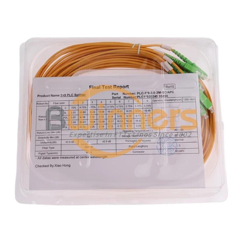
1×9 70/30 Unbalanced PLC Splitter, SC/APC, ABS Cassette, 3 m

Cassette PLC Splitter