BWNF-PLC-ABS-1×3-70-30-SCAPC-3M
Cassette PLC Splitter
1×3 Unbalanced PLC Splitter, 70/15/15, SC/APC ABS, 3 m
This 1×3 unbalanced PLC splitter provides one nominal 70% cascade path and two nominal 15% tap paths, with SC/APC connectors and 3 m leads in an ABS module.

Proposed model: BWNF-PLC-ABS-1×3-70-30-SCAPC-3M — TBC: formal SKU-to-report mapping required
This 1×3 unbalanced PLC splitter has one input, one nominal 70% output and two nominal 15% outputs in a protected ABS module. The supplied build record identifies G657A fiber, 3.0 mm × 3 m pigtails, SC/APC terminations and a 1260–1650 nm operating window. Use the model-specific port map and approved optical limits; do not substitute an equal-split 1×3 table or a 1×3 FBT coupler.
Browse the broader cassette PLC splitter family, review PLC splitter selection fields, or return to the fiber optic splitter product directory when this exact build does not match the requirement.
Primary CTA — Request a model and test-record review: Send the target topology, required port assignment, loss budget, host enclosure, quantity and delivery location. BWNFiber will return the proposed model mapping, available drawing/datasheet, model-specific acceptance limits and quotation status after internal confirmation.
What Does 70/30 Mean on This 1×3 Model?
For the photographed build, 70/30 is a shorthand for three outputs: output 1 is marked 70%, while outputs 2 and 3 are each marked 15%. The two tap outputs therefore share the remaining 30%. This interpretation is specific to the supplied report and physical labels; it should not be assumed for another 1×3 splitter without its approved port map.
| Physical label | Intended role | Nominal share | Validation action |
|---|---|---|---|
| IN | Input | 100% input reference | Match the input label to the BOM/drawing |
| 70% | Higher-share output | 70% | Confirm whether the design assigns it to the continuing path |
| 15% | Tap output 1 | 15% | Budget with the approved path-specific loss limit |
| 15% | Tap output 2 | 15% | Budget with the approved path-specific loss limit |
The optical budget must use loss values, not nominal percentages alone. The network designer must add fiber, splice, connector, splitter and engineering-margin losses for every complete path and compare the result with the approved OLT/ONU or equipment power limits.
Verified Configuration of the Photographed Build
| Attribute | Supplied evidence | Publication condition |
|---|---|---|
| Product type | 1×3 PLC splitter | Confirm commercial SKU mapping |
| Factory part number | PLC-1*3-3.0-3M-SC/APC | Retain exact punctuation from approved record |
| Output assignment | 70% / 15% / 15% | Confirm production labels and drawing |
| Fiber | G657A | Do not add A1/A2 subtype without evidence |
| Pigtail | 3.0 mm, 3 m | Verify against approved order drawing |
| Connector | SC/APC | Four connectorized tails are visible |
| Operating wavelength | 1260–1650 nm | Treat as report value for this build |
| Package dimensions | 100 × 80 × 10 mm | Verify mechanical drawing before enclosure release |
| Operating/storage temperature | −40 to +85 °C | Confirm qualification method and model applicability |
| Return loss | 55 dB minimum on supplied report | Confirm whether this is a model acceptance limit |
| Directivity | 55 dB minimum on supplied report | Confirm whether this is a model acceptance limit |
Measured Serial Example at 1310 and 1550 nm
The supplied Final Test Report records the following measurements for serial PLC1*320240 95461. These are traceability data for that photographed build, not universal limits for every unit or a substitute for the approved model specification.
| Output | Nominal share | IL at 1310 nm | PDL at 1310 nm | IL at 1550 nm | PDL at 1550 nm |
|---|---|---|---|---|---|
| 1 | 70% | 1.92 dB | 0.18 dB | 1.73 dB | 0.11 dB |
| 2 | 15% | 8.97 dB | 0.15 dB | 8.90 dB | 0.07 dB |
| 3 | 15% | 8.90 dB | 0.18 dB | 8.97 dB | 0.08 dB |
Before publication or PO release, QA must confirm the measurement scope, equipment/method, calibration traceability, whether connector loss is included, the applicable acceptance limits and whether the serial may be shown publicly.
Where This Splitter Fits
This configuration may fit a designed optical-distribution route that needs one higher-share continuation path and two lower-share local branches. The network diagram must identify the intended role of every output and prove that all resulting paths remain inside the equipment power budget.
Do not select this model only because 70/30, 1×3 or SC/APC appears in a BOM. Also confirm:
- PLC rather than FBT technology;
- the 70/15/15 port convention and physical labels;
- operating wavelength and required optical limits;
- G657A fiber and 3.0 mm × 3 m pigtails;
- connector family and APC polish at every mating interface;
- ABS-module dimensions, cable exits and routing clearance;
- the complete end-to-end optical budget and required margin.
Non-fit conditions
Do not use this page to approve:
- an equal-split 1×3 or 1×4 design;
- a 1×3 FBT coupler selected for a different wavelength window or coupling function;
- a design that requires a different connector, fiber grade, tail diameter/length or enclosure;
- a path that has not been checked against model-specific loss limits;
- a compliance or environmental requirement that is not covered by the approved product packet.
PLC and FBT Are Not Interchangeable Labels
BWNFiber already publishes a separate 1×3 FBT product with overlapping SC/APC, 3.0 mm, 3 m and 70:30 ordering language. That does not make it a direct substitute for this proposed PLC model. Release either item only after the BOM identifies the technology, wavelength requirement, output convention, path-specific optical limits, package and test evidence.
For a technology comparison, use the dedicated PLC-vs-FBT guide. This page is limited to the exact proposed PLC configuration.
The existing 1×3 SC/APC FBT splitter record remains a separate technology-specific product page.
How to Validate the Model Before an RFQ or Purchase Order
- Fix the identity. Confirm the commercial SKU, factory part number and revision on the same approved record.
- Fix the port map. Mark IN, 70%, 15% and 15% on the drawing and physical labels.
- Close every path budget. Use the approved maximum loss for each output, plus fiber, connector, splice and margin assumptions.
- Confirm the interface. Match SC/APC with the mating adapters and patch cords; do not mix APC and UPC interfaces.
- Confirm mechanical fit. Check the module envelope, tail exits, routing space and bend control in the intended box or cabinet.
- Define acceptance evidence. State whether the order requires a datasheet, drawing, serial report, label sample, end-face record or other inspection file.
- Freeze the PO description. Put the exact ratio convention, port labels, fiber, tail, connector, package, optical limits, quantity and revision on the order.
RFQ Input Checklist
Send the following information:
- proposed model or reference part number;
- network diagram and the role of the 70% and 15% paths;
- operating wavelengths and equipment optical classes;
- maximum allowed loss for each complete path and required margin;
- 1×3, 70/15/15 output assignment;
- G657A requirement, including subtype if required;
- 3.0 mm pigtail diameter and 3 m length, or approved alternatives;
- SC/APC on input and all outputs;
- ABS module envelope and host-enclosure constraints;
- required drawing, datasheet, serial test report and label format;
- quantity, sample requirement, delivery location and target schedule.
Secondary CTA — Request the product packet: Ask for the approved SKU mapping, drawing/datasheet, model acceptance table and available serial-level test documentation before a sample or batch PO.
Documents and Evidence
| Document | Current page status |
|---|---|
| Approved SKU-to-factory-part mapping | TBC — source required |
| Model datasheet | TBC — source required |
| Mechanical drawing with port map | TBC — source required |
| Model-specific optical acceptance limits | TBC — source required |
| Serial Final Test Report | Photograph supplied; publication and scope approval required |
| GR-1209/GR-1221 qualification evidence | TBC — source required; no compliance claim in this draft |
| Image-use authorization | TBC — rights confirmation required |
FAQ
1×3 Unbalanced PLC Splitter, 70/15/15, SC/APC ABS, 3 m FAQ
Is 70/30 the same as 70/15/15 on every 1×3 splitter?
No. On the supplied build, the report and labels show one 70% output and two 15% outputs. Another supplier or model may use different ratio notation. Confirm the approved port map before budgeting or ordering.
Which port continues to the next distribution point?
The physical 70% label identifies the higher-share output on the supplied unit. Whether that port should continue to another distribution point is a network-design decision and must be shown on the approved route diagram.
Can I use an equal-split 1×3 loss value?
No. The three paths do not carry equal nominal shares. Use the approved path-specific limits for the exact model or serial record, then close the complete end-to-end budget.
Do the measured values on this page apply to every unit?
No. The displayed values belong to the photographed serial example. Model acceptance limits and the report shipped or approved for the ordered unit control procurement and acceptance.
Can the existing BWNFiber 1×3 FBT 70:30 product replace this PLC model?
Not by description alone. PLC and FBT identify different component technologies and may have different wavelength behavior, package, port convention and optical limits. Compare the approved BOM and product records before substitution.
What must be confirmed before requesting a quote?
Confirm technology, 1×3 port map, 70/15/15 assignment, wavelength, loss limits, fiber, pigtail diameter/length, connectors, package, host enclosure, documents, quantity and schedule.
Related Products
Related Products
Explore additional fiber optic products related to this item and suitable for similar network deployment needs.

Cassette PLC Splitter
1×9 80/20 Uneven PLC Splitter, SC/APC, 3.0 mm × 3 m ABS Module

Cassette PLC Splitter
1×9 75/25 Unbalanced PLC Splitter with SC/APC and 3 m Leads
Cassette PLC Splitter
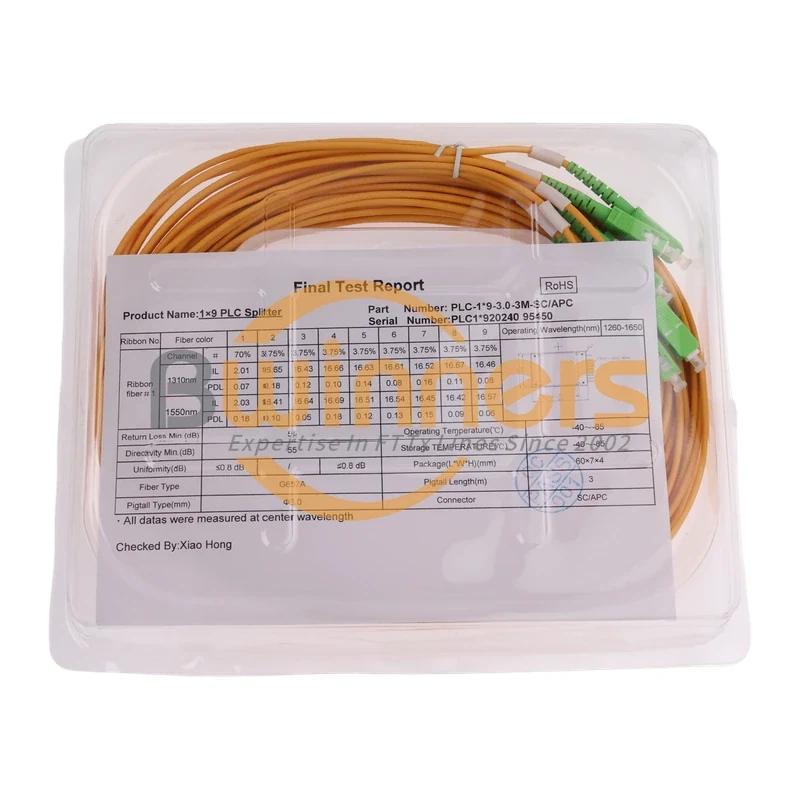
1×9 70/30 Unbalanced PLC Splitter, SC/APC, ABS Cassette, 3 m

Cassette PLC Splitter