BWN-PLC-MMST-1X2-NA-0.25-U9010
Bare Fiber PLC Splitter
1×2 90/10 Unbalanced Bare-Fiber PLC Splitter, 250 µm, Unterminated
A compact 1×2 90/10 unbalanced PLC splitter with G.657.A1 250 µm unterminated leads and separate higher-power and tap paths.

90/10 configuration at a glance
The BWN-PLC-MMST-1X2-NA-0.25-U9010 is a 1×2 unbalanced PLC splitter with nominal 90% and 10% output paths. The inspected build uses G.657.A1 250 µm unterminated leads, no connectors, a compact 40 × 4 × 4 mm package and lead lengths recorded as at least 1.0 m.
The two outputs must be budgeted separately. The ratio identifies nominal power distribution; it is not an insertion-loss value, and balanced 50/50 limits must not be substituted for this model.
Recorded configuration
| Attribute | Recorded value |
|---|---|
| Configuration | 1 input × 2 outputs, unbalanced 90/10 |
| Fiber | G.657.A1, 250 µm |
| Connector | None / unterminated |
| Lead length | At least 1.0 m on the inspected record |
| Package | 40 × 4 × 4 mm on the inspected sheet |
| Operating wavelength | 1260–1650 nm |
| Operating / storage temperature | −40 °C to +85 °C |
| PDL | 0.20 dB maximum on the inspected sheet |
| Return loss / directivity | >55 dB / >55 dB on the inspected sheet |
Port-specific optical limits
| Output | Nominal role | Maximum insertion loss on inspected sheet |
|---|---|---|
| 90% | Higher-power / lower-loss path | 1.40 dB |
| 10% | Lower-power / higher-loss path | 11.80 dB |
The photographed sample recorded 90% path insertion loss of 1.18, 1.00 and 1.13 dB at 1310, 1490 and 1550 nm. The 10% path recorded 11.26, 11.18 and 11.24 dB. These are sample-specific readings, not universal guaranteed values. Use the approved purchase specification and the report tied to the delivered unit or lot for acceptance.
Integration and selection checks
- Confirm the physical 90% and 10% output labels before splicing.
- Calculate both paths with connector, splice, fiber and engineering margins.
- Verify the 40 × 4 × 4 mm package and lead routing against the host tray or enclosure.
- Protect the unterminated 250 µm leads with suitable routing, bend control and environmental protection.
- State the ratio, lead construction, length, quantity, destination and document requirements in the RFQ.
RFQ information
Send the intended topology, required 90/10 port convention, host enclosure, route loss budgets, quantity and destination. Request the current model datasheet, dimensional drawing, port map and applicable optical test record before final BOM approval.
FAQ
1×2 90/10 Unbalanced Bare-Fiber PLC Splitter, 250 µm, Unterminated FAQ
How are the 90% and 10% outputs used?
The 90% output is the higher-power, lower-loss path and the 10% output is the lower-power, higher-loss path. Assign both labels in the route schedule before installation.
Are the sample measurements guaranteed limits?
No. The readings belong to the inspected sample. Production acceptance must use the approved model or purchase-order limits and the report supplied with the delivered unit or lot.
Does this product include connectors?
No. The inspected configuration uses unterminated leads intended for controlled splicing or integration inside a suitable tray, closure or distribution enclosure.
Can a different split ratio replace the 90/10 model?
Not without design approval. A different ratio changes the loss on both paths and requires a new optical-budget calculation.
Related Products
Related Products
Explore additional fiber optic products related to this item and suitable for similar network deployment needs.

Cassette PLC Splitter
1×9 80/20 Uneven PLC Splitter, SC/APC, 3.0 mm × 3 m ABS Module

Cassette PLC Splitter
1×9 75/25 Unbalanced PLC Splitter with SC/APC and 3 m Leads
Cassette PLC Splitter
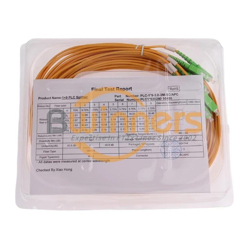
1×9 70/30 Unbalanced PLC Splitter, SC/APC, ABS Cassette, 3 m

Cassette PLC Splitter