BWNF-PLC-ABS-1×17-80-20-SCAPC-3M
Cassette PLC Splitter
1×17 80/20 Unbalanced PLC Splitter with SC/APC and 3 m Leads
This connectorized 1×17 PLC splitter uses one 80% path and sixteen 1.25% tap paths. The photographed assembly is identified as factory P/N PLC-B-1X17-3.0-3M-SC/APC and uses SC/APC connectors, G657A fiber, 3.0 mm pigtails and a 3 m reported length. It is not an equal 1×17 splitter, and it is not the same configuration as BWNFiber’s published 1×17 70/30 steel-tube model.

This connectorized 1×17 PLC splitter uses one 80% path and sixteen 1.25% tap paths. The photographed assembly is identified as factory P/N PLC-B-1X17-3.0-3M-SC/APC and uses SC/APC connectors, G657A fiber, 3.0 mm pigtails and a 3 m reported length. It is not an equal 1×17 splitter, and it is not the same configuration as BWNFiber’s published 1×17 70/30 steel-tube model.
Primary action: Request the current datasheet, dimensional drawing and serial-matched optical report.
Submit: required quantity, exact ratio string, connector/polish, pigtail diameter and length, host-enclosure space, port-label plan, target loss budget and required compliance documents.
BWNFiber response, subject to internal approval: a configuration review and quotation package showing the proposed model, controlled specification, drawing, report availability, commercial terms and unresolved exceptions.
Short answer for buyers
Use this 1×17 unbalanced PLC splitter only when the approved network design calls for one higher-power 80% path plus sixteen lower-power 1.25% paths. Confirm the physical port labels, host-enclosure fit and worst-route optical budget before ordering. The readings below belong to photographed serial 2024095454; they are sample results, not universal production guarantees.
Key points
- 1 input and 17 outputs: one 80% path plus sixteen nominal 1.25% paths.
- SC/APC connectors are shown on the photographed assembly and named on its test report.
- The report lists G657A fiber, 3.0 mm pigtails, 3 m length and a 1260–1650 nm operating wavelength.
- The report lists a 120 × 80 × 18 mm package for the photographed unit. Request the current drawing before approving enclosure fit.
- Per-port insertion loss and PDL were recorded at 1310 nm and 1550 nm for serial
2024095454. - Housing material: TBC — source required. Treat
ABSas unverified until an approved drawing, BOM or controlled datasheet confirms it. - GR-1209-CORE, GR-1221-CORE and RoHS conformity: TBC — exact-model evidence required. A logo or family-page claim is not qualification evidence.
Product identification and verified configuration
| Field | Draft value | Evidence status |
|---|---|---|
| Commercial SKU | BWNF-PLC-ABS-1x17-80-20-SCAPC-3M | TBC — reconcile with factory label |
| Factory P/N on photographed unit | PLC-B-1X17-3.0-3M-SC/APC | Verified for serial 2024095454 |
| Configuration | 1 × 17 unbalanced PLC splitter | Verified for photographed unit |
| Ratio string | 80/1.25×16 | Verified for photographed unit |
| Connector | SC/APC | Verified for photographed unit |
| Fiber | G657A | Verified for photographed unit; A1/A2 not stated |
| Pigtail type | 3.0 mm | Verified for photographed unit |
| Reported pigtail length | 3 m | Verified for photographed unit |
| Operating wavelength | 1260–1650 nm | Report-listed for photographed unit |
| Reported package size | 120 × 80 × 18 mm | Report-listed; drawing required for fit approval |
| Housing material | Black cassette; material TBC | Source required |
| Report-listed operating/storage temperature | −40 °C to +85 °C | Qualification method not supplied |
| Report-listed return loss/directivity | 55 dB minimum / 55 dB minimum | Test method and production limits require confirmation |
How the 80/20 ratio maps to 17 outputs
80/20 is the two-group ratio, not the number of output ports. On the photographed unit, one path is marked 80%, while sixteen paths are each marked 1.25%. Sixteen times 1.25% equals the remaining 20% nominal allocation.
| Path group | Quantity | Nominal share per path | Total nominal share | Procurement role |
|---|---|---|---|---|
| Higher-power path | 1 | 80% | 80% | Candidate onward/through path, subject to the approved topology |
| Tap paths | 16 | 1.25% | 20% | Candidate local branches, subject to the route budget |
Do not order or label the unit as simply “1×17 PLC.” The RFQ, drawing, product label, port map and purchase order should all carry the complete 80/1.25×16 ratio string.
Measured optical results for the photographed sample
The following values were transcribed from the supplied Final Test Report for serial 2024095454, dated 2024-09-28. The report states that data were measured at center wavelength. Engineering must confirm the test method, instrument, connector boundary and transcription before publication.
| Path | Nominal share | IL at 1310 nm (dB) | PDL at 1310 nm (dB) | IL at 1550 nm (dB) | PDL at 1550 nm (dB) |
|---|---|---|---|---|---|
| Higher-power path | 80% | 2.12 | 0.15 | 2.09 | 0.06 |
| Tap 1 | 1.25% | 19.60 | 0.14 | 19.75 | 0.13 |
| Tap 2 | 1.25% | 19.66 | 0.12 | 19.63 | 0.07 |
| Tap 3 | 1.25% | 19.71 | 0.10 | 19.59 | 0.18 |
| Tap 4 | 1.25% | 19.69 | 0.12 | 19.58 | 0.09 |
| Tap 5 | 1.25% | 19.66 | 0.20 | 19.58 | 0.07 |
| Tap 6 | 1.25% | 19.70 | 0.06 | 19.69 | 0.17 |
| Tap 7 | 1.25% | 19.89 | 0.10 | 19.60 | 0.13 |
| Tap 8 | 1.25% | 19.75 | 0.07 | 19.89 | 0.08 |
| Tap 9 | 1.25% | 19.75 | 0.14 | 19.68 | 0.10 |
| Tap 10 | 1.25% | 19.88 | 0.06 | 19.80 | 0.19 |
| Tap 11 | 1.25% | 19.68 | 0.17 | 19.71 | 0.14 |
| Tap 12 | 1.25% | 19.62 | 0.13 | 19.66 | 0.10 |
| Tap 13 | 1.25% | 19.83 | 0.16 | 19.72 | 0.08 |
| Tap 14 | 1.25% | 19.62 | 0.10 | 19.81 | 0.10 |
| Tap 15 | 1.25% | 19.59 | 0.14 | 19.74 | 0.15 |
| Tap 16 | 1.25% | 19.67 | 0.12 | 19.70 | 0.19 |
For this sample, the tap-path IL spans 19.59–19.89 dB at 1310 nm and 19.58–19.89 dB at 1550 nm. Use the approved maximum limits for the ordered build—not these sample minima/maxima—when closing a route budget. Obtain the report that matches the delivered serial number for acceptance.
Application and compatibility conditions
This configuration may fit a cascaded or tap-based passive optical distribution design when one route must retain a larger nominal power share and sixteen lower-power routes serve local branches. Suitability is conditional on the complete link budget, the active equipment limits, wavelength plan, connector/splice losses, fiber distance, engineering margin and every splitter stage.
Before approval:
- Define which physical output is the 80% path and verify the label sequence.
- Calculate every route, including the highest-loss tap, connectors, splices, fiber and engineering margin.
- Confirm that the host enclosure accepts the current cassette drawing, pigtail-exit direction, service slack and connector-routing space.
- Confirm SC/APC throughout the mating path. Do not mate APC and UPC interfaces.
- Match the quoted model, drawing revision, product label, purchase order and report.
For topology selection and general unbalanced-splitter planning, use the site’s dedicated guide rather than expanding this SKU page into a broad tutorial. For package-family selection, see the cassette PLC splitter range and PLC splitter guide and products.
If the design calls for the published 70/30 steel-tube configuration instead, review the 1×17 70/30 uneven PLC splitter family and do not substitute its optical values for this 80/20 cassette build.
When this product is not a fit
- The design needs 17 equal-power outputs.
- The design specifies 70/30, 75/25 or another ratio instead of 80/20.
- The available enclosure space has not been checked against an approved drawing.
- The network requires UPC interfaces, a different connector family, or an unterminated splice-in module.
- The link budget cannot accommodate the worst approved tap-path loss plus the rest of the route.
- The project requires environmental, GR, RoHS or other compliance evidence that has not been supplied for the exact model and revision.
- The buyer is still deciding between PLC and FBT technology or among topology options; that decision belongs in the relevant selection guide, not in an exact-SKU substitution.
How this configuration differs from related products
| Product role | Ratio/package | Use this page when… | Use another owner when… |
|---|---|---|---|
| This exact SKU | 1×17, 80/1.25×16, connectorized black cassette, SC/APC, 3.0 mm, 3 m | The approved BOM calls for this exact configuration | Any listed attribute changes |
| Existing BWNFiber 1×17 family page | Published 1×17 70/30 steel-tube/mini-module family | The project calls for the published 70/30 build or family customization | The request is the exact 80/20 cassette build |
| Cassette PLC category | Multiple 1×N/2×N cassette options | The buyer is comparing channel counts, dimensions or interfaces | The buyer already selected this exact SKU |
| Unbalanced PLC guide | Multiple ratios/topologies | The buyer needs topology, sequence or budget guidance | The buyer needs a quote/report for this SKU |
| Even 1×16 or 1×32 PLC | Equal outputs | Equal division is required | A higher-power through path is required |
Test and document package to request
The release package for an order should identify the model and revision and, where applicable, include:
- controlled product datasheet;
- current dimensional drawing and pigtail-exit orientation;
- approved port map and label convention;
- production optical limits and test conditions;
- serial-matched IL/PDL report at the agreed wavelengths;
- requested material or compliance evidence for the exact model and scope;
- packing/label requirements and the agreed inspection plan.
The supplied photograph is evidence for one sample. It must not be presented as a blanket certificate or as proof that every future unit will reproduce the same readings.
RFQ checklist
Send the following in one request:
- quantity and project/location reference;
- commercial SKU, if already approved;
- exact configuration:
1×17, 80/1.25×16; - SC/APC connector quantity and mating-interface requirements;
- fiber grade requirement; do not assume A1 or A2 when the document only states G657A;
- 3.0 mm pigtail construction and 3 m length, or the requested alternatives;
- available cassette space, mounting method and routing clearance;
- physical port-label sequence and which path continues downstream;
- route loss budget and required production maximums;
- required datasheet, drawing, test report, compliance and packing documents;
- target delivery date and destination for quotation.
FAQ
1×17 80/20 Unbalanced PLC Splitter with SC/APC and 3 m Leads FAQ
What does 80/20 mean on a 1×17 splitter?
On the photographed build, one path is nominally 80% and sixteen paths are nominally 1.25% each. The complete ratio is therefore 80/1.25×16. It is not a 17-way equal split.
Are the measured values production specifications?
No. They are readings from serial 2024095454. Use an approved controlled specification for production limits and a serial-matched report for delivered-unit acceptance.
Which output should continue to the next distribution point?
The approved topology may assign the 80% path as the onward path, but the physical port and label must match the drawing and port map. Do not infer it from connector position alone.
Does the page prove that the housing is ABS?
Not yet. The supplied product naming says ABS, but the release package does not include a controlled material drawing or BOM. Keep the material as TBC — source required until approved evidence is provided.
Can this replace an even 1×16 or 1×17 splitter?
No automatic substitution is valid. An even splitter distributes power differently and has no equivalent 80% path. Recalculate the topology and obtain engineering approval before any substitution.
Does the product meet GR-1209-CORE, GR-1221-CORE or RoHS requirements?
Exact-model evidence was not supplied in this review. Request the applicable qualification report or declaration and confirm model, revision, scope and validity before publishing or ordering against those requirements.
What should be checked before placing the RFQ?
Confirm the exact ratio, port map, connector/polish, fiber, pigtail diameter and length, cassette drawing, loss budget, required production limits, documents, quantity and delivery destination.
Related Products
Related Products
Explore additional fiber optic products related to this item and suitable for similar network deployment needs.

Cassette PLC Splitter
1×9 80/20 Uneven PLC Splitter, SC/APC, 3.0 mm × 3 m ABS Module

Cassette PLC Splitter
1×9 75/25 Unbalanced PLC Splitter with SC/APC and 3 m Leads
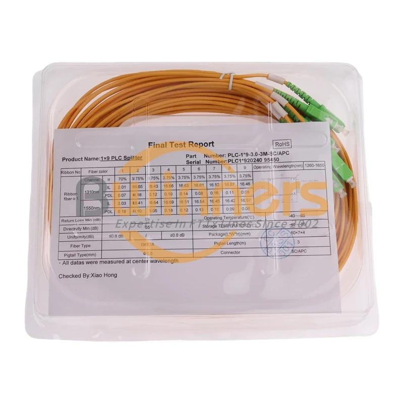
Cassette PLC Splitter
1×9 70/30 Unbalanced PLC Splitter, SC/APC, ABS Cassette, 3 m

Cassette PLC Splitter