BWN-PLC-MMST-1×16-NA-0.9mm
Bare Fiber PLC Splitter
1×16 Blockless Mini PLC Splitter, 0.9 mm, 2 m, No Connector
Model: BWN-PLC-MMST-1×16-NA-0.9mm Status: TBC — model-to-factory-P/N mapping and catalog limits require approval.

Model: BWN-PLC-MMST-1×16-NA-0.9mm
Status: TBC — model-to-factory-P/N mapping and catalog limits require approval.
This 1×16 PLC splitter uses a compact steel-tube package with one unterminated input lead and sixteen color-coded unterminated output leads. The photographed sample is marked for 0.9 mm fiber, 2 m length and no connectors. It is intended for integration inside a protected splice tray, distribution box or closure after the host fit, routing and optical budget are approved.
Primary action: Request the current model datasheet, dimensional drawing and optical acceptance limits.
Secondary action: Send the host-tray drawing or BOM for configuration review.
Quick Product Answer
BWN-PLC-MMST-1×16-NA-0.9mm is a steel-tube, 1×16 equal PLC splitter supplied without connectors. The photographed unit has 0.9 mm, 2 m leads and a serial-specific 1310/1550 nm test report. Before ordering, confirm the controlled datasheet, exact G.657 fiber subtype, package drawing, host-tray clearance and project loss limits.
Key Configuration
| Order field | Draft value | Evidence state |
|---|---|---|
| Public model | BWN-PLC-MMST-1×16-NA-0.9mm | TBC — mapping approval required |
| Split configuration | 1 input × 16 outputs, equal | Pictured report; catalog approval required |
| Package | Blockless mini steel tube | Visually observed |
| Package size | 60 × 12 × 4 mm | Pictured report; confirm drawing |
| Fiber | G.657A | TBC — specify A1 or A2 |
| Lead construction | 0.9 mm, color-coded outputs | Visually observed/report; confirm material |
| Lead length | 2 m | Pictured marking/report; confirm tolerance and input/output datum |
| Connector | None; unterminated | Visually observed |
| Operating band | 1260–1650 nm | Pictured report; approve catalog value |
| Operating/storage temperature | −40 to +85 °C | Pictured report; qualification method TBC |
What the No-Connector Configuration Changes
This model does not ship with SC, LC or FC connectors. The input and output leads must be fusion-spliced or terminated as defined by the project work package. The installer is responsible for protecting splices, maintaining approved bend control, identifying all sixteen outputs and verifying the complete installed path. Do not apply connector-polish claims to the unterminated assembly itself.
Serial-Specific Optical Evidence
The supplied photo shows a final test report for serial PLC1*162024049725. The table below is a transcription of that pictured report and is sample evidence for that serial only. It is not the catalog acceptance specification for every production unit.
| Port | IL 1310 nm (dB) | PDL 1310 nm (dB) | IL 1550 nm (dB) | PDL 1550 nm (dB) |
|---|---|---|---|---|
| P1 | 13.29 | 0.16 | 13.09 | 0.19 |
| P2 | 13.12 | 0.11 | 13.02 | 0.14 |
| P3 | 13.31 | 0.16 | 13.04 | 0.16 |
| P4 | 13.27 | 0.15 | 13.35 | 0.09 |
| P5 | 13.11 | 0.07 | 13.06 | 0.07 |
| P6 | 13.21 | 0.16 | 13.38 | 0.08 |
| P7 | 12.99 | 0.10 | 13.22 | 0.06 |
| P8 | 13.34 | 0.17 | 13.29 | 0.15 |
| P9 | 13.40 | 0.10 | 13.38 | 0.09 |
| P10 | 13.31 | 0.18 | 13.01 | 0.07 |
| P11 | 13.14 | 0.15 | 13.15 | 0.07 |
| P12 | 13.25 | 0.11 | 13.23 | 0.09 |
| P13 | 13.23 | 0.14 | 13.11 | 0.05 |
| P14 | 13.39 | 0.16 | 13.09 | 0.18 |
| P15 | 13.22 | 0.18 | 13.13 | 0.16 |
| P16 | 13.32 | 0.19 | 13.04 | 0.08 |
The pictured report also lists 0.40 dB uniformity at 1310 nm, 0.37 dB at 1550 nm, 50 dB minimum return loss and 55 dB minimum directivity. TBC: Optical QA must confirm the report, method, instrument/calibration, reference conditions and approved production acceptance limits before these values are exposed as model claims.
Integration and Compatibility Conditions
- Use the steel-tube module only inside a host tray, box or closure that provides fixation, bend control, strain management and environmental protection.
- Confirm 60 × 12 × 4 mm body clearance against the approved dimensional drawing, including fiber exits and cover clearance.
- Confirm splice-protector capacity, fiber routing and service-loop space for one input and sixteen outputs.
- Confirm the exact G.657 subtype and minimum bend radius from the approved fiber specification.
- Validate every planned PON path against the project loss budget. A 1×16 split does not by itself prove GPON or XGS-PON compatibility.
- Treat the steel tube as an internal component, not as a standalone outdoor/IP-rated enclosure.
For family-level integration criteria, review the blockless mini PLC splitter options. Use the GPON splitter selection guide for topology and interface decisions and the splitter loss and link-budget guide for path calculations.
Choose This Model When
- The approved design calls for one input and sixteen equal outputs.
- The host enclosure accepts a 60 × 12 × 4 mm steel-tube module and nineteen routed leads.
- Fusion splicing or field termination is part of the installation plan.
- A connectorized cassette, LGX module or rack panel is not required.
Do not choose this model when the project requires factory-installed connectors, plug-and-play replacement, a standalone weatherproof package or a different split ratio.
Difference from Related 1×16 Products
| Product form | Termination | Host requirement | Use when |
|---|---|---|---|
| This model: steel-tube 1×16 NA | No connectors; 0.9 mm leads | Protected tray/box/closure with splice management | The installer will splice or terminate the leads |
| Connectorized blockless mini 1×16 | SC/LC/FC, APC/UPC as ordered | Tray/box with adapter and bend clearance | Factory connectors are required |
| Cassette/ABS 1×16 | Protected module, usually pigtails/connectors | Compatible module bay or box | Handling and replacement need more protection |
| Rack-mounted 1×16 | Front-panel ports | 19-inch rack/ODF | Centralized access and patching are required |
For technology-level evaluation rather than this exact SKU, use the PLC vs FBT splitter comparison.
Testing, Inspection and Release
Before order release, agree on the catalog acceptance limits and the report format for insertion loss, uniformity, PDL, return loss and directivity. On receipt, verify the model/serial, lead count and identification, steel-tube condition, lead length, connector state, report-to-serial match and any project-specific optical acceptance criteria. A photographed sample report does not replace an approved purchase specification.
Packaging and Procurement
- Unit packaging:
TBC — source required - Quantity per package:
TBC — source required - MOQ, price, stock and lead time:
TBC — quotation required - Warranty:
TBC — source required - Available document pack:
TBC — confirm datasheet, drawing and serial/lot test report
What to Send for an RFQ
- Model or approved equivalent: BWN-PLC-MMST-1×16-NA-0.9mm.
- 1×16 equal split and intended PON/cascade context.
- Host tray, distribution box or closure model and available clearance.
- Required fiber subtype, lead diameter, input/output length and length tolerance.
- Unterminated ends and planned splice/termination method.
- Project maximum IL, uniformity, PDL, return-loss and directivity limits with test wavelengths.
- Label/port map, serial or lot traceability and required report format.
- Quantity, destination, target schedule and packaging/document requirements.
Primary CTA: Request the Current Datasheet, Drawing and Optical Limits
Send the host-enclosure drawing, loss budget and quantity. BWNFiber should return a configuration-matched document pack and quotation after Product/QA approval.
Downloads
- Model datasheet:
TBC — approved file required - Dimensional drawing:
TBC — approved file required - Sample or unit test report:
TBC — approved redacted file required
FAQ
1×16 Blockless Mini PLC Splitter, 0.9 mm, 2 m, No Connector FAQ
Is this a bare-fiber PLC splitter?
Not under the current BWNFiber taxonomy. The photographed unit has a steel-tube package and 0.9 mm leads, so it should be classified as a blockless mini PLC splitter. Bare fiber should remain with the separate no-steel-tube form factor unless Product Management changes the taxonomy.
Does this model include connectors?
No connectors are visible, and the pictured marking uses NA. Confirm the approved order record before release. The installation plan must define fusion splicing or field termination and protection for every lead.
Can the pictured IL/PDL table be used as the guaranteed specification?
No. It is a serial-specific test record. Use an approved datasheet or purchase specification for production acceptance limits, then compare each shipped report with those limits.
Will it fit any 1×16 splice tray?
No. Confirm the body drawing, fiber-exit direction, bend control, service-loop space, splice-protector capacity and cover clearance against the actual host tray or enclosure.
Is it automatically compatible with GPON or XGS-PON?
No. A passive 1×16 configuration may be used in a compatible PON design, but the network engineer must approve wavelengths, total path loss, cascade arrangement, equipment class and operating margin.
Which documents should be approved before a bulk order?
Approve the exact model/part-number mapping, datasheet, dimensional drawing, port identification, purchase specification, test-report format, label proof and packaging requirements.
Related Products
Related Products
Explore additional fiber optic products related to this item and suitable for similar network deployment needs.

Cassette PLC Splitter
1×9 80/20 Uneven PLC Splitter, SC/APC, 3.0 mm × 3 m ABS Module

Cassette PLC Splitter
1×9 75/25 Unbalanced PLC Splitter with SC/APC and 3 m Leads
Cassette PLC Splitter
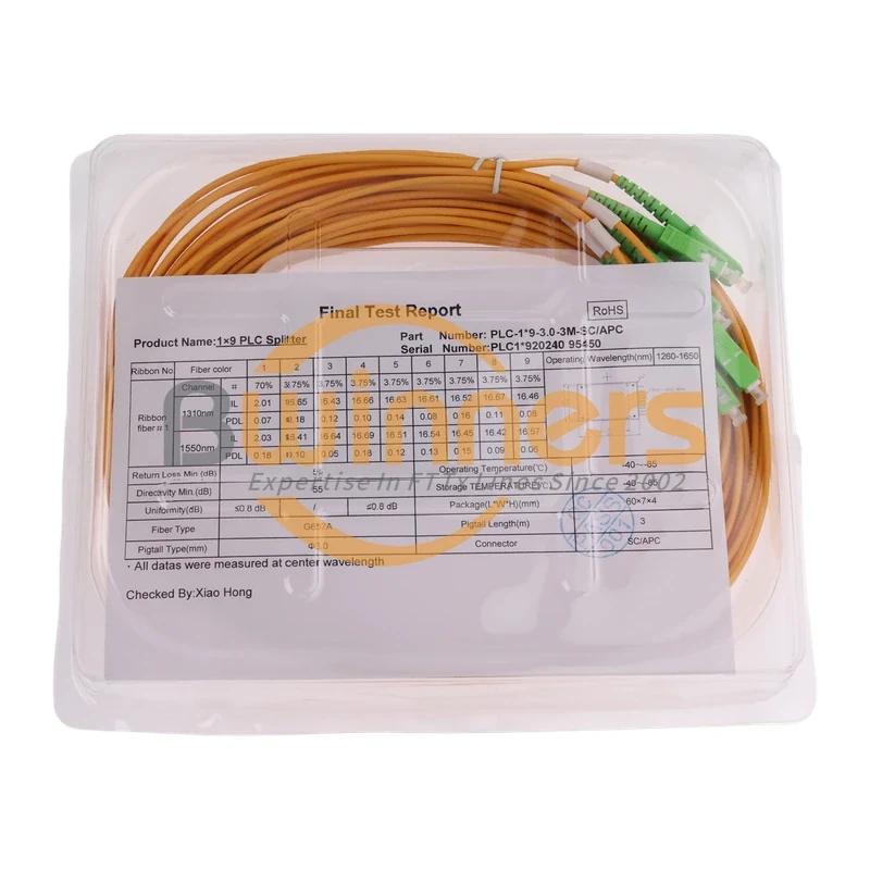
1×9 70/30 Unbalanced PLC Splitter, SC/APC, ABS Cassette, 3 m

Cassette PLC Splitter