A few years ago, an ISP in Hanoi was about to sign off a new FTTH backbone. Every span had passed the installer’s continuity check with a visual fault locator. Then the customer’s engineer ran an insertion loss test at 1550 nm, and one 6 km section failed. The crew found a cable tie cinched too tight in a riser closet and one connector that had never been cleaned. Together they added about 3 dB of loss — enough to erase the maintenance margin and stall the handover for a week.
That difference is what fiber optic cable testing catches. This field acceptance manual covers installation, the three tests that prove the link, and how to verify the loss budget before handover. It is written for FTTH project managers, ISP contractors, telecom EPC teams, and data center operators who need the link to work the first time and the paperwork to back it up.
Quick answer: Fiber optic cable testing is the set of continuity, insertion loss, and OTDR measurements that prove an installed link meets its loss budget. A link is ready for handover when the measured loss at every wavelength sits below the calculated budget with at least 3 dB of margin.
Working through an acceptance test right now? Send your route length, splitter ratio, and measured readings to [email protected] and we will check them against the loss budget.

What You Will Learn
- How to plan a fiber installation: route, pulling tension, splice points, and bend radius
- The three mandatory fiber optic cable tests: continuity, insertion loss, and OTDR
- How to verify an optical power budget and a PON loss budget against field measurements
- How to clean and inspect connectors so they do not become the weakest link
- The field mistakes that cause hidden failures and acceptance delays
- What to put in a fiber link handover folder before you leave site
For procurement teams: Specify fiber type, cable construction, and installation method before requesting quotes, and require per-drum factory test reports — batch averages can hide a failing drum. Hold acceptance to quantified limits: measured loss under 80% of the calculated budget, splices at or below 0.15 dB after re-test, and return loss above 45 dB on UPC (hold new builds to 50 dB). Keep three documents for handover: the test report, the OTDR traces, and the loss budget calculation. Request samples and verify them on your own OLTS before bulk production.
Fiber Optic Cable Installation: The Basics
Good fiber installation is 80% preparation and 20% execution. Before any cable leaves the reel, you need a route plan, pulling tension limits, splice locations, and a calculated loss budget. Skipping any of these four items is how projects end up with broken fibers, excess loss, or cables that do not fit the closure.
Route Planning
Every fiber run has a maximum pulling tension. Exceed it and you stretch or break the glass. Typical limits are:
- Short indoor pulls: 100–200 N during installation
- Long outdoor duct pulls: up to 600 N for some cables, but always check the datasheet
- Aerial spans: tension calculated from span length, wind load, and ice load
Plan splice points every 2–4 km for long outdoor runs. Fewer splices mean lower loss, but you also need reachable locations for closures and future maintenance. For the right cable construction for your route, see the fiber optic cable product range.
Pulling Fiber Cable
For duct pulls, use a pulling eye attached to the strength member, not the jacket. Apply pulling lubricant to reduce friction. Never pull around sharp corners without a pulley or guide. For direct burial, use a trench deep enough for local codes — usually 60–120 cm depending on the region and surface type.
Aerial cable needs the right amount of sag. Too tight and wind load breaks the cable. Too loose and it swings into obstacles. ADSS and figure-8 cables come with sag-tension charts from the manufacturer.
Match the Cable Construction to the Route
Cable construction matters as much as fiber type. For outdoor duct, aerial, and burial routes I specify loose-tube cable: the fibers sit in gel- or dry-blocked tubes, so temperature swings and cable movement do not stress the glass, and one cable carries anything from 12 to 288 fibers. For indoor risers and equipment rooms, tight-buffered cable with a flame-retardant LSZH jacket is the right call — it terminates directly and meets indoor fire codes.
Outdoor jackets are UV-stabilized polyethylene (PE). Do not put an indoor cable outdoors — sunlight and temperature will age the jacket within a season. Direct burial in rocky or rodent-prone ground calls for armored construction, steel tape or wire armor, or at minimum a rodent-resistant jacket. The small cost difference is cheaper than one excavation.
Whatever construction you choose, confirm it against IEC 60794 cable specifications and the actual project environment before ordering. Temperature range, water exposure, and installation method all change the right answer.
Bend Radius Rules
Every cable has a minimum bend radius. As a practical rule:
- Under tension: 20 times the cable outer diameter
- After installation: 10 times the cable outer diameter
G.657.A1/A2 bend-insensitive fiber helps indoors and in tight splice trays, but it does not remove the need for proper routing. G.652.D is still the workhorse for outside plant and long-haul links where bend radius is less critical.
Fiber Optic Cable Testing: Three Mandatory Tests
A fiber link needs three levels of proof before handover: continuity, insertion loss, and OTDR. Continuity tells you the fiber is not broken. Insertion loss tells you whether the link will carry traffic. OTDR tells you where the events are and whether each splice or connector is within spec.
1. Continuity Test
Continuity is the quickest test and the least informative. Shine a visible laser through the fiber and confirm light exits the far end. A visual fault locator (VFL) also helps find sharp bends or breaks because the light leaks out at the fault.
This test tells you the fiber is not broken. It does not tell you if the link will work at the target speed and distance. I use it during pulling and rough-in, not as a final acceptance test.
2. Insertion Loss Test
Insertion loss testing measures how much light is lost end-to-end. You need a calibrated light source and a fiber optic power meter, or an Optical Loss Test Set (OLTS) that combines both in one unit. On small jobs, a handheld fiber cable tester with a built-in VFL covers continuity and rough loss checks; for formal acceptance, use a separate light source and meter pair. That pair is the minimum fiber optic test equipment for acceptance work; add an OTDR when the contract requires event documentation. Test at both 1310 nm and 1550 nm for single-mode fiber, and at 850 nm and 1300 nm for multimode fiber. Some operators also test at 1625 nm, because it supports later live-fiber monitoring without dropping customer traffic.
Measure per IEC 61300-3-4: connect the source and meter directly, store the reference, then measure at the far end and compare. Match the reference method to what you certify: one reference cord for a connector-to-connector plant, three cords when the link includes the equipment patch cords. For multimode plants, use encircled-flux-compliant test cords per TIA-526-14 — without a controlled launch, two test sets can report different losses on the same link. Record the baseline loss against your loss budget. I have seen links that looked fine at 1310 nm and failed at 1550 nm because of a stress bend the first test never saw. If the measured loss is close to or over the budget, find the problem before you hand over the link. This is the test that decides whether the link will actually carry traffic.
3. OTDR Test
An Optical Time Domain Reflectometer (OTDR) sends a pulse down the fiber and plots reflections and backscatter. It shows:
- Total link length
- Location of splices and connectors
- Bend or break locations
- Uniformity of loss across the link
- Return loss at each reflective event
I always run a bi-directional OTDR from both ends for runs over 1 km. A one-direction OTDR can hide events. Bi-directional averaging gives the true splice loss at each point and catches false gains.
Two setup details decide whether your OTDR trace holds up in a dispute. First, connect a launch cable — a 300–500 m reference spool — between the OTDR and the link. Without it, the event dead zone after the launch pulse hides the first connector, and I have watched a customer reject a handover over exactly that gap. Second, use a receive cable at the far end so the last connector is measured, not guessed. Good OTDR testing practice is simple: launch cable, receive cable, both directions, and record return loss per IEC 61300-3-6.
| Test | What It Tells You | Best For | Tool |
|---|---|---|---|
| Continuity / VFL | Fiber is intact, no major breaks | During installation, quick troubleshooting | Visual fault locator |
| Insertion loss | Total end-to-end loss | Acceptance testing, commissioning | Light source + optical power meter / OLTS |
| OTDR | Event locations, splice quality, bend points, return loss | Long links, fault location, documentation | OTDR with launch and receive cables |
One more distinction matters when you read a scope of work: Tier 1 vs Tier 2 fiber testing. Tier 1 is insertion loss and length measured with a light source and power meter — the acceptance baseline for most FTTH and premises projects. Tier 2 adds an OTDR trace analyzed event by event against set limits, which carriers, data centers, and warranty-backed builds often require. If a contract says “certification” instead of “testing,” confirm the tier before you price the job; Tier 2 takes roughly twice the field time.
My test setup rule for underground routes: VFL during pulling, OTDR before the trench is closed or the duct sealed, and full insertion loss testing at acceptance. This catches bad splices before burial, where fixing them costs many times more.
How to Calculate Optical Loss Budget
The loss budget is the maximum allowed loss for a link. It sets the rules for how many splices, connectors, and kilometers of fiber you can have before the receiver can no longer see the signal clearly.
Basic Formula
Total allowable loss = Transmitter output power − Receiver sensitivity − Safety margin
A typical safety margin is 3 dB. It leaves room for aging, connector dirt, future repairs, and measurement uncertainty. That last item is not trivial: field measurements carry ±0.2–0.5 dB of uncertainty depending on the reference method, so a link measuring 0.1 dB under budget is not really under budget. In harsh or hard-to-access environments, use 4–5 dB.
Typical Loss Values
| Component | Typical Loss | Notes |
|---|---|---|
| Single-mode fiber at 1310 nm | 0.35 dB/km | Per ITU-T G.652 / G.657 |
| Single-mode fiber at 1550 nm | 0.22 dB/km | Per ITU-T G.652 / G.657 |
| Multimode fiber at 850 nm | 3.0 dB/km | OM3/OM4/OM5 typical |
| Multimode fiber at 1300 nm | 1.0 dB/km | OM3/OM4/OM5 typical |
| Fusion splice | 0.05–0.10 dB | Requires good cleave and protection |
| Mechanical splice | 0.20–0.50 dB | Higher, but field-friendly |
| Connector pair (UPC) | 0.30–0.50 dB | IEC 61300-3-4 compliant |
| Connector pair (APC) | 0.30–0.50 dB | Lower reflection, better return loss |
Standards set the ceiling; your field targets should sit well below it. TIA-568 and ISO/IEC 11801-1 acceptance limits allow up to 0.75 dB per mated connector pair and 0.30 dB per fusion splice. On a new build I flag anything above 0.50 dB per connector or 0.10 dB per splice for a re-test, and a splice that still reads above 0.15 dB after re-test stops the handover (see the red flags below). The tighter numbers leave room for aging, repairs, and the next crew that works on the link.
Example Calculation
A 10 km single-mode link at 1310 nm with 2 connector pairs and 4 splices:
- Fiber loss: 10 km × 0.35 dB/km = 3.50 dB
- Connectors: 2 × 0.30 dB = 0.60 dB
- Splices: 4 × 0.08 dB = 0.32 dB
- Subtotal: 4.42 dB
- Safety margin: 3.00 dB
- Required budget: 7.42 dB
If your optical transceiver has a power budget of 28 dB (GPON Class B+), this link has plenty of headroom. If the budget is only 9 dB, you are cutting it close and should reduce splices or use better connectors.
PON Loss Budget Example
FTTH networks use Passive Optical Network (PON) technology. A single fiber from the Optical Line Terminal (OLT) is split to serve many customers. The loss budget must include fiber loss, splitter loss, connectors, splices, and a maintenance margin.
| Component | Loss / Budget |
|---|---|
| GPON Class B+ | 28 dB total budget |
| GPON Class C+ | 32 dB total budget |
| 1:16 splitter | ~14 dB |
| 1:32 splitter | ~17.5 dB |
| 1:64 splitter | ~21 dB |
| Fiber at 1310 nm | 0.35 dB/km |
| Connector pair | 0.30–0.50 dB |
| Fusion splice | 0.08 dB typical |
| Maintenance margin | 3 dB minimum |
These splitter values are typical maxima from ITU-T G.671-based datasheets: premium bare 1×32 devices come in near 17.0 dB, while standard or connectorized modules run 17.5–17.7 dB. The ideal split loss is 10·log₁₀(N) — 12.0 dB for 1:16, 15.0 dB for 1:32, 18.1 dB for 1:64 — so a splitter measuring far above these numbers carries excess loss and will eat your margin.
For GPON Class B+ (28 dB budget), a 1:32 split over 10 km fits on paper but often lands within about 1 dB of the limit once you count every connector and the 3 dB reserve. Class C+ (32 dB budget) gives you room for longer feeder runs or a 1:64 split. Always model the worst-case path, not the average. Use an optical power budget calculator or a simple spreadsheet to check every scenario before you commit to the splitter ratio.
Working through a loss budget for a live project? Send us the route length, fiber type, and splitter ratio — we will model the budget and flag the risks before you order cable or splitters. 📧 [email protected]
Fiber Optic Cleaning Guide
Dirty connectors are the most common cause of high insertion loss and return loss. A single particle of dust can block the entire 9 µm core of a single-mode fiber. Cleaning is not optional — it is part of the test.
Inspection and Cleaning Steps
- Inspect the connector end face with a fiber microscope or inspection probe.
- If dirty, clean with a lint-free wipe and approved solvent, or use a click cleaner.
- Inspect again after cleaning.
- Do not touch the end face with bare fingers.
- Clean every connector before mating, every time.
| Step | Action | Why It Matters |
|---|---|---|
| Inspect | Use 200x–400x fiber scope, grade to IEC 61300-3-35 | Finds dust, oil, chips, cracks |
| Dry clean | Lint-free wipe or click cleaner | Removes loose contamination |
| Wet-dry clean | Approved solvent + wipe | Removes oil and stubborn residue |
| Re-inspect | Confirm end face is clean | Prevents high loss and damage during mating |
| Mate | Push straight, no twisting | Avoids scratching and core misalignment |
That discipline takes 30 seconds per connector and prevents hours of troubleshooting. For cleaning supplies and inspection tools, see fiber optic testing tools.
Fusion Splicing Fiber Optic Cable
Fusion splicing is the standard way to join fibers in outside-plant and FTTH networks. A good fusion splice adds less than 0.1 dB of loss. A bad splice — caused by dirty cleaves, poor alignment, or unprotected joints — can add 0.5 dB or more and fail under temperature cycling.
Why Fusion Splicing Matters for Loss
Every splice is a permanent loss point. In a 10 km link with four splices, the difference between 0.05 dB and 0.20 dB per splice is 0.6 dB — almost 10% of a GPON Class B+ budget. Good splicing pays back in margin and reliability.
On a provincial FTTH project in the Peruvian highlands, we found 11 of 240 splices above 0.15 dB after the first cold snap of the season. Every one of them sat in a closure where the sleeve had slipped before the heat shrink fully bonded; the temperature swing did the rest. Rework took one day. The alternative was a winter of intermittent customer complaints that would have been almost impossible to trace.
Splice Protection
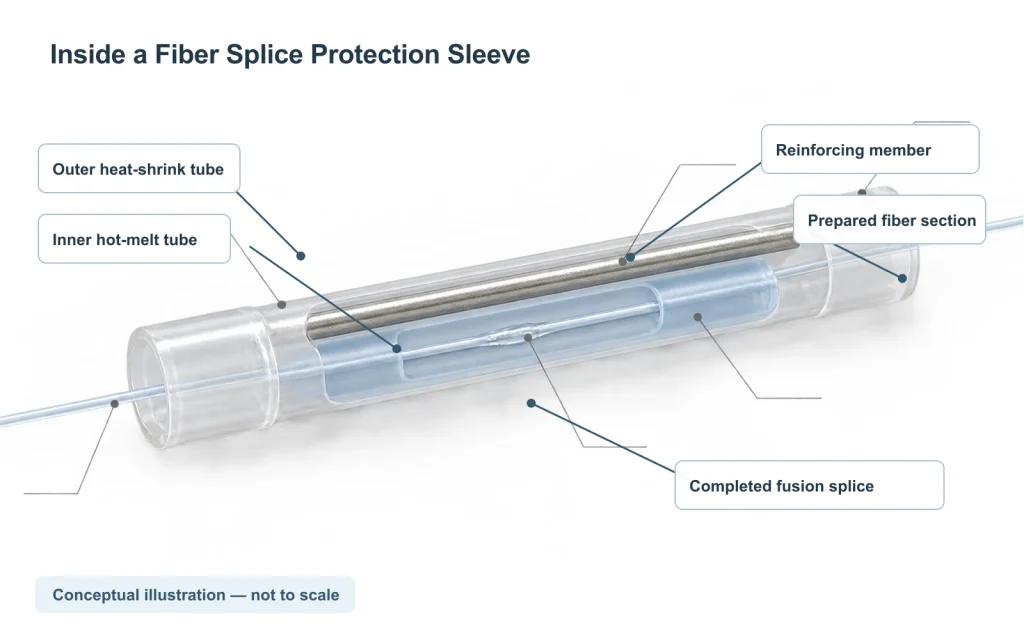
After splicing, the joint must be protected in a splice closure or tray. A fiber optic splice protection sleeve keeps the splice straight, seals it from moisture, and provides mechanical strength. Without it, the splice is the first place the link will fail when temperature changes or the cable moves.
Installation Mistakes That Cost Projects
- Pulling by the jacket. The strength member carries the load. Pulling the jacket can separate the cable layers and strain the fibers.
- Exceeding bend radius. A tight zip-tie or sharp corner can add permanent microbending loss.
- Skipping bi-directional OTDR. One-way OTDR readings can miss high-loss splices or show false gains.
- No loss budget before ordering. If you do not know your power budget, you cannot choose the right transceivers or splitter ratio.
- Dirty connectors. This alone causes more field failures than any cable defect.
- Wrong fiber type for the route. G.657.A2 handles tight bends indoors; G.652.D is better for long outside-plant runs.
- Ignoring drum damage on arrival. The cable is rated for crush loads; the drum flange often is not. Check every reel before you accept the shipment and note damage on the delivery receipt.
FTTH Installation Notes
FTTH access networks live or die on the drop segment. Three field rules I follow on every project:
- Use bend-insensitive drop cable (G.657.A2) on the last stretch into the building. Indoor routing around corners is where standard G.652.D picks up microbending loss.
- Leave 2–3 m service loops at every closure and drop terminal. Future repairs need slack, and retrofitting it is expensive.
- Test each drop end-to-end after the ONT is installed, not before. A connectorized drop is only as good as its last mating.
The PON budget table above applies here: count the full path from the OLT to the farthest ONU — not the average drop — including splitter loss and every connector, before you fix the splitter ratio. XGS-PON uses similar budget classes to GPON but runs at 10 Gbps, where there is less tolerance for sloppy splices — keep the same 3 dB maintenance margin and treat the budget as a hard ceiling.

Data Center Installation Notes
Data center links are short but dense. Pre-terminated MPO/MTP trunks save time and reduce field termination errors. Key points:
- Use polarity-managed cables for 40G/100G/400G, and confirm the polarity method (Type A, B, or C) against the design before you label the trunk. Polarity mismatches are the most common cause of failed 40G/100G turn-ups.
- Label both ends of every trunk.
- Keep patch cords neat and within bend radius.
- Test every channel with a power meter or MPO-capable OLTS, not just continuity. One dirty MPO end face can take down all 12 or 24 fibers in a trunk at once.
In a data center, the cost of downtime far exceeds the cost of good testing. We test 100% of links and keep the reports for future troubleshooting.
Acceptance Testing Checklist
Use this checklist before you hand over a fiber link:
- [ ] Route verified against drawings, splice locations accessible
- [ ] Bend radius checked at every turn, tie point, and tray entry
- [ ] All connectors cleaned and inspected before mating
- [ ] Continuity confirmed with VFL or light source
- [ ] Insertion loss tested at required wavelengths (1310/1550 nm SM, 850/1300 nm MM)
- [ ] Measured loss is within the calculated loss budget
- [ ] Bi-directional OTDR run from both ends for links over 1 km
- [ ] OTDR trace saved and events labeled with distances and loss values
- [ ] Return loss recorded for reflective events
- [ ] Test reports delivered to the project owner
How to Hand Over a Fiber Link
A clean handover protects the installer and the customer. I do not sign off a link until the acceptance test report, the route record, and the loss budget match. Here is the workflow I use on FTTH and telecom projects.
Before the Crew Leaves Site
- Collect the route record. Note cable type, fiber count, route length, splice locations, and closure positions.
- Save all test data. Keep insertion loss readings, OTDR traces in both directions, and end-face inspection photos.
- Check every connector. One dirty connector at the patch panel can fail the whole link on commissioning day.
- Compare measured loss to the loss budget. If measured loss is within 3 dB of the transceiver limit, flag the link for review.
What Goes Into the Handover Folder
| Document | Why It Matters |
|---|---|
| Test report | Proves the link meets acceptance criteria |
| OTDR trace | Documents every event and splice location |
| Route record | Helps future crews find splices and closures |
| Loss budget calculation | Shows the design margin and assumptions |
| Cable datasheets | Confirms fiber type and attenuation specs |
Want the folder as a template? Email [email protected] and we will send the handover checklist PDF we use on project sites.
Red Flags That Delay Handover
- Measured insertion loss is more than 80% of the calculated link budget.
- OTDR shows a splice over 0.15 dB or a connector over 0.5 dB.
- Return loss measures below 50 dB on UPC or 60 dB on APC — 45 dB is the UPC floor, and a new build should not start there.
- The route record does not match the as-built drawings.
Fix these before the customer runs their own test. It is almost always cheaper to rework a link while the crew and equipment are still on site.
What to Request From Your Fiber Supplier
Testing discipline also applies to procurement. When you source cable, splitters, or accessories for a project, ask the supplier for these documents before you commit — they become part of the handover folder your customer signs against. A supplier who answers quickly has done it before:
| Document | What to Check |
|---|---|
| Cable datasheets | Fiber type, attenuation at 1310/1550 nm, jacket material (PE outdoor, LSZH indoor) matches the route |
| Factory test reports | Per-drum attenuation and length values, not just batch averages |
| Component certificates | Connector IL/RL grades, splitter compliance with ITU-T G.671 |
| Sample approval | Test samples against your own OLTS before bulk production |
At BWNFiber we provide datasheets, per-drum factory test reports, and pre-production samples as standard practice. Our engineers ask for the route length, installation method, and environment before recommending a construction — a recommendation without route data is a guess. For export orders, we confirm drum packaging, reel labeling, and shipping documents with the quotation, so the consignment arrives with the paperwork your customs broker and project folder need. Request the documents with your quotation.
Procurement Mistakes That Come Back at Acceptance
Price tactics and quote comparison belong in the buying guide. These four mistakes are different: they pass quietly at purchase and return on test day.
- Accepting batch-average test data. Averages can hide one bad drum. Per-drum attenuation values are the only numbers that let you challenge a failing span at acceptance.
- Skipping sample approval. Test samples on your own OLTS before production starts. A day of checking beats a container that misses the specification.
- Leaving the route environment out of the inquiry. Temperature swings, water exposure, UV, and rodents choose the construction. State them, or you will receive the standard design — which may not survive its first season on the route.
- Not asking about small customizations. Custom fiber counts, sheath materials, or drum lengths often add days, not weeks, and can remove field splices, scrap, and installation hours from the project.
For quote comparison and pricing factors, see the fiber optic cable buying guide.
Frequently Asked Questions
Q: What is the most important fiber test?
A: Insertion loss testing. It tells you whether the link meets the power budget and will actually carry traffic reliably.
Q: How often should I clean fiber connectors?
A: Before every mating. Even a connector that was clean yesterday can collect dust sitting in a patch panel.
Q: Can I use a VFL instead of an OTDR?
A: A VFL finds breaks and sharp bends up to a few kilometers. It cannot measure loss or locate events precisely. Use an OTDR for acceptance testing and long links.
Q: What is a good safety margin for loss budget?
A: 3 dB is standard. In harsh or hard-to-access environments, use 4–5 dB to leave room for future repairs.
Q: Why do acceptance standards require both 1310 nm and 1550 nm?
A: Macro-bends leak far more light at 1550 nm. A link can pass at 1310 nm and still fail its budget at 1550 nm — I catch one or two of these on most large projects. Add 1625 nm if the link will be monitored live later.
Q: Insertion loss vs return loss: which one fails a link at acceptance?
A: Insertion loss decides the pass/fail — measured end-to-end loss must stay under the loss budget. Return loss is a separate quality gate: below 45 dB on UPC or 60 dB on APC means reflection problems that bite PON upstream and high-speed links even when insertion loss looks fine. On new builds I hold UPC links to 50 dB so aging has somewhere to go.
Q: Do I need an OLTS and an OTDR?
A: For most acceptance testing, you need an OLTS or light-source-and-power-meter set to measure insertion loss. OTDR adds fault location and documentation. Many projects require both.
Q: What is a normal fusion splice loss?
A: A good fusion splice is typically 0.05–0.10 dB. If you are consistently seeing more than 0.15 dB, check your cleaver, electrode condition, and fiber alignment.
Q: How do you pass an insertion loss test at handover?
A: Zero the meter against the light source at each wavelength (the IEC 61300-3-4 reference method), keep test leads short and clean, and document every reading. The link passes when each wavelength’s measured loss sits below the calculated budget — with margin to spare, not just under the line.
Q: What is the difference between Tier 1 and Tier 2 fiber testing?
A: Tier 1 measures insertion loss and length with a light source and power meter. Tier 2 adds an OTDR trace analyzed event by event. Most FTTH acceptance is Tier 1 plus OTDR documentation; carriers and data centers often require full Tier 2.
Q: What standards govern fiber optic cable testing?
A: TIA-526-7 (single-mode) and TIA-526-14 (multimode) define the insertion loss test methods, TIA-568.3-D sets the Tier 1 and Tier 2 certification framework, and IEC 61300-3-4, 61300-3-6, and 61300-3-35 cover insertion loss, return loss, and end-face inspection. For PON builds, the ITU-T G.984.2 budget classes set the pass/fail line.
Q: Is OTDR testing too expensive for small sites?
A: For a handful of short links, a fiber cable tester that combines light source, power meter, and VFL is enough. For longer runs, rent an OTDR with proper launch cables or bring in a contractor — one rejected handover costs more than the rental.
Q: Should the supplier handle all the testing?
A: The supplier should provide factory test data for what they ship. Field acceptance testing belongs to the installer or project owner, because it proves what was actually installed. Keep both sets of documents in the handover folder.
Q: What documents should I request from a fiber supplier?
A: Cable datasheets, per-drum factory test reports, component certificates (connector IL/RL, splitter G.671 compliance), and samples for approval before bulk production.
Q: What procurement mistakes cause acceptance failures?
A: Four repeat offenders: accepting batch-average test data instead of per-drum values, skipping sample approval before production, leaving the route environment out of the inquiry so the construction does not match the installation, and ordering standard designs where a small customization would remove field splices. Every one of them surfaces on test day, when fixing it costs the most.
Q: How long does fiber acceptance testing take?
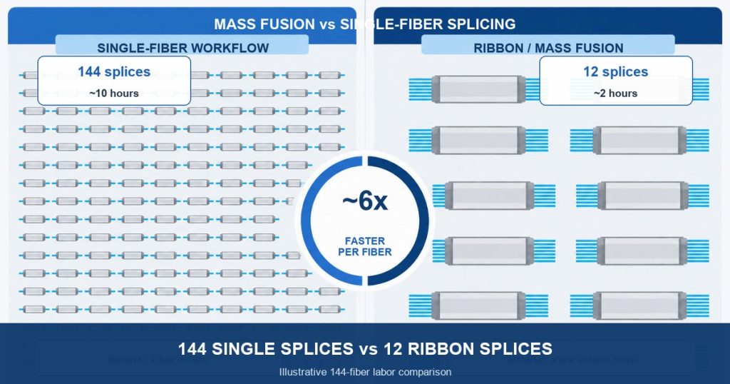
A: A single FTTH drop takes 15–30 minutes including cleaning and documentation. A 144-fiber backbone takes a full day with a two-person crew — half of it OTDR and power-meter work, the other half cleaning, labeling, and paperwork. Budget for the paperwork; it is what the customer actually signs.
Q: Who pays for rework when a link fails acceptance?
A: Whoever signed the acceptance test report without catching the failure. If the installer hands over without measured loss data, the rework cost lands on the installer. Fix the link while the crew and equipment are still on site — a return visit costs several times more than the same fix on day one.
Standards & References
- ITU-T G.652 — single-mode fiber attenuation characteristics
- ITU-T G.657 — bend-insensitive single-mode fiber
- ITU-T G.984.2 — GPON physical layer, Class B+ (28 dB) and Class C+ (32 dB) budgets
- ITU-T G.671 — transmission characteristics of passive optical components
- IEC 61300-3-4 / 61300-3-6 / 61300-3-35 — insertion loss, return loss, and end-face inspection methods (iec.ch)
- IEC 60794 series — optical fiber cable construction and test specifications (iec.ch)
- ANSI/TIA-526-7 and TIA-526-14 — single-mode and multimode insertion loss test methods
- ANSI/TIA-568 and ISO/IEC 11801-1 — premises cabling acceptance limits
Related Reading
- Fiber Optic Cable Types: Complete Selection Guide
- Fiber Optic Cable Buying Guide: Price, Standards & Selection
- FTTH Drop Cable & Aerial/Underground Fiber Cable Guide
- How to Install, Heat Shrink & Use Fiber Splice Protection Sleeves
- Fiber Optic Connector Types and Color Codes Guide
- Fiber Optic Cable Testing: OTDR, Power Meter & Best Practices

Need Fiber Testing or Installation Support?
BWNFiber supplies fiber optic cables (including custom and OEM designs), splice protection sleeves, connectors, patch cords, and testing accessories for telecom, FTTH, and data center projects. For project-based cable selection, send your fiber count, route environment, and installation method — our engineers will recommend a construction and model the loss budget before you order.
Request with your quotation: cable datasheets · per-drum factory test reports · pre-production samples
Related BWNFiber products: fiber optic testing tools · fiber optic cables · fiber optic splice protection sleeves
📧 [email protected]
📞 +86-13615744790 (WhatsApp)
🌐 www.bwnfiber.com
About the author: The BWNFiber Network Engineering Team designs, tests, and ships fiber optic cable systems for FTTH, ISP, telecom, and data center projects. Field questions: [email protected].
This guide is for internal reference and project planning. Data as of 2026-09-01.
BWNFiber · Business Intelligence Excellence